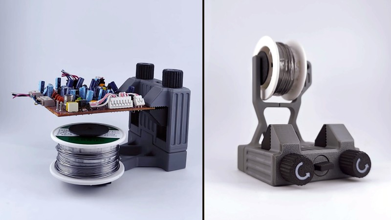
Needing less than 70 grams of filament, [Chefkoch]’s 3D printed PCB vise solder station might be a good way to use up some filament spool leftovers and get yourself a handy tool in return.
What we like about this design is that it is multi-functional, and cleverly uses the solder spool as a counterweight to add stability that might otherwise be lacking in such a compact design.
The assembly can be reconfigured so that the jaws are either horizontal or vertical; the solder spool is held conveniently either way. The whole thing is 3D printed, so there’s no other hardware or fasteners involved. It’s probably best suited to small boards, but it’s also compact, entirely 3D printed, and doesn’t need much filament.
Still have some filament left over and want a nifty solder feeder to go with it? Check out the solder scroll, a pen-like DIY tool that makes handheld solder feeding a little less of a hassle.
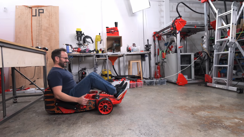
[Ivan Miranda] is famous for his large-scale 3D printed vehicles. They’re pretty fun, but they’re also pretty big and heavy—which can make transporting them around rather impractical. Hence, when he had reason to travel with a 3D printed go kart, he went back to the drawing board to create something light enough to pack in regular plane luggage.
The build started with some major compromises compared to [Ivan]’s previous go kart build. Notably, there are only three wheels instead of four, and a simplified control layout that eschews a regular steering wheel. These decisions were made to save weight and allow the design to be more compact. The kart uses a set of handles either side of the rider to handle steering. Drive is via a brushless motor, with power supplied from a series of 18 V drill batteries. Parts were produced on [Ivan]’s massive printer which comes in handy on large-scale projects like these.
All in all, the final build weighed around 20 kg. That’s light enough to be broken down across checked luggage and carry-on for a typical flight. We’d consider the project a success on that basis, even if quite a bit of assembly was required upon arriving at the destination. [Ivan]’s other builds in this realm are pretty fun too, from the printed scooter to the ride-on tank.
The weather is warming up, and for many of us that means more time spent working out in the yard. You probably won’t find any new life or new civilizations out there, but if you’ve spent the last few months indoors on your computer, the garden may as well be a strange new world. In that case, you’d do well to equip the members of your landing party with this Star Trek: The Original Series hose sprayer designed by [Curt Turner].
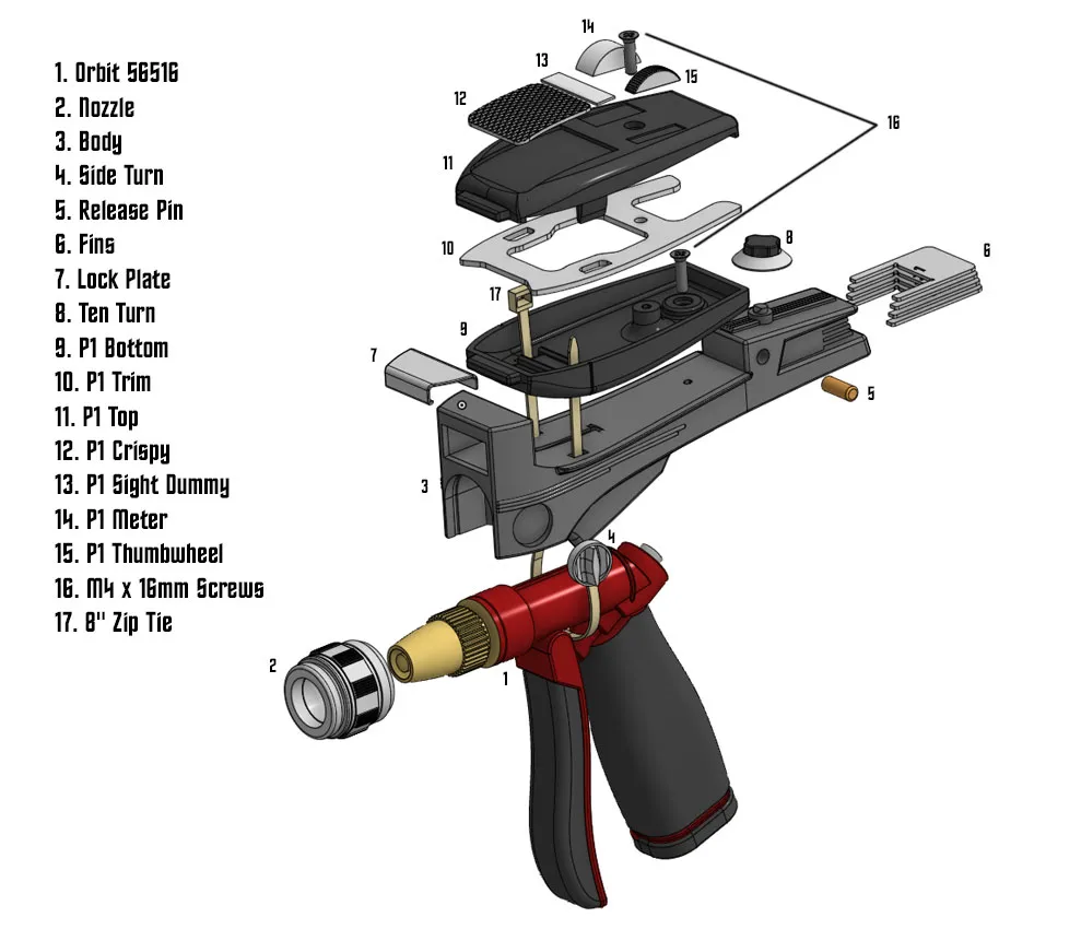
If you’re wondering how [Curt] managed to 3D print a functional hose sprayer, the short answer is that he didn’t. Once assembled, the printed parts cleverly attach to the top of a standard sprayer, specifically the model 56516 “Pro Flo” from Orbit. Without the design constraints that would have come from trying to make the thing actually contain pressurized water, [Curt] was free to focus on the aesthetics, and it shows.
Even with a garden variety — no pun intended — sprayer strapped to the bottom, it’s remarkable how much the “Sprayser” looks like the real thing. Well, not real, but you know what we mean.
[Curt] has also done an excellent job documenting this project for others that want to imagine they’re fighting off Romulans in their backyard. He’s got assembly diagrams that break down which color each of the principle components is to be printed in, as well as a build video that we’ve embedded below.
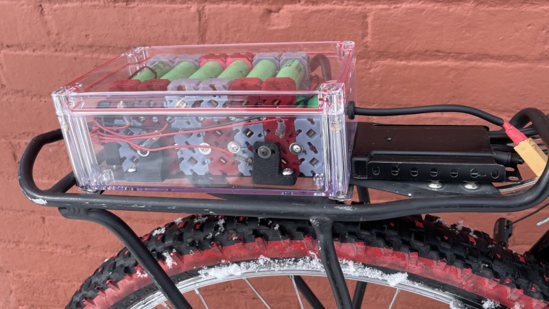
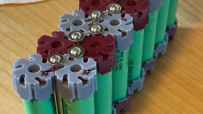
Building a battery pack from 18650 cells traditionally requires patience, a spot welder, and a supply of nickel strip. But what if there was another way? [Ben] is here with Cell-Lock, a modular battery assembly system.
At the system’s heart are a set of interlocking end caps and connection pieces that function as locking cams as well as the electrical connections where needed. They were inspired by the cam systems used for furniture assembly, and are activated by rotation with a screwdriver. The result is a mechanically stable battery system in which different configurations can easily be assembled.
We like that it doesn’t involve any heat near those cells; in part because we’ve seen our share of dodgy connections overheating. But we do have a few concerns. These include how reliable a connection those cams would make, as well as how much current they could safely take without overheating. If both of those could be addressed, we can see that this is an idea with a future.
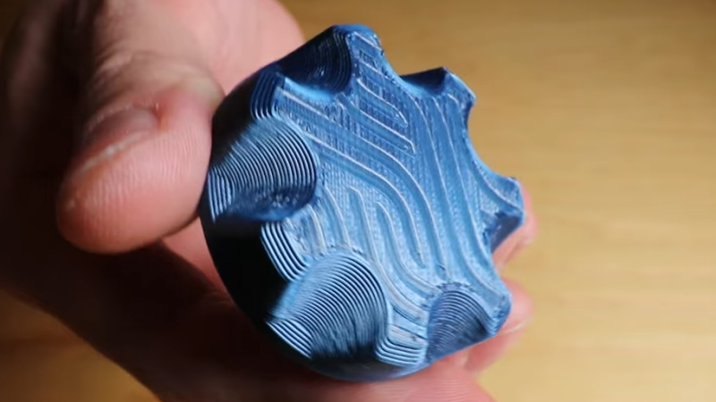
While working on a project that involved super-thin prints, [Julius Curt] came up with selective ironing, a way to put designs on the top surface of a print without adding any height.
For those unfamiliar, ironing is a technique in filament-based 3D printing that uses the extruder to smooth out top surfaces after printing them. The hot nozzle makes additional passes across a top surface, extruding a tiny amount in the process, which smooths out imperfections and leaves a much cleaner surface. Selective ironing is nearly the same process, but applied only in a certain pattern instead of across an entire surface.
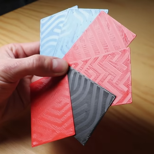
Selective Ironing can create patterns by defining the design in CAD, and using a post-processing script.
While conceptually simple, actually making it work was harder than expected. [Julius] settled on using a mixture of computer-aided design (CAD) work to define the pattern, combined with a post-processing script. More specifically, one models the desired pattern into the object in CAD as a one-layer-tall feature. The script then removes that layer from the model while applying the modified ironing pattern in its place. In this way, one can define the pattern in CAD without actually adding any height to the printed object. You can see it in action in the video, embedded below.
We’ve seen some interesting experiments in ironing 3D prints, including non-planar ironing and doing away with the ironing setting altogether by carefully tuning slicer settings so it is not needed. Selective Ironing is another creative angle, and we can imagine it being used to embed a logo or part number as easily as a pattern.
Selective Ironing is still experimental, but if you find yourself intrigued and would like to give it a try head over to the GitHub repository where you’ll find the script as well as examples to try out.
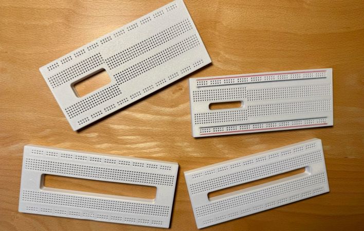
Although off-the-shelf breadboards are plentiful and cheap, they almost always seem to use the same basic design. Although you can clumsily reassemble most of them by removing the voltage rail section and merging a few boards together, wouldn’t it be nice if you had a breadboard that you could stick e.g. one of those wide ESP32 development boards onto and still have plenty of holes to poke wires and component leads into? Cue [Ludwin]’s 3D printable breadboard design that adds a big hole where otherwise wasted contact holes would be.
The related Instructables article provides a visual overview of the rationale and the assembly process. Obviously only the plastic shell of the breadboard is printed, after which the standard metal contacts are inserted. These contacts can be ‘borrowed’ from commercial boards, or you can buy the contacts separately.
For the design files there is a GitHub repository, with breadboard designs that target the ESP32, Raspberry Pi Pico, and the Arduino Nano. An overview of the currently available board designs is found on the Hackaday.io project page, with the top image showing many of them. In addition to the single big space design there are also a few variations that seek to accommodate just about any component and usage, making it rather versatile.
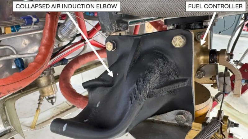
Back in March, a small aircraft in the UK lost engine power while coming in for a landing and crashed. The aircraft was a total loss, but thankfully, the pilot suffered only minor injuries. According to the recently released report by the Air Accidents Investigation Branch, we now know a failed 3D printed part is to blame.
The part in question is a plastic air induction elbow — a curved duct that forms part of the engine’s air intake system. The collapsed part you see in the image above had an air filter attached to its front (towards the left in the image), which had detached and fallen off. Heat from the engine caused the part to soften and collapse, which in turn greatly reduced intake airflow, and therefore available power.
Serious injury was avoided, but the aircraft was destroyed.
While the cause of the incident is evident enough, there are still some unknowns regarding the part itself. The fact that it was 3D printed isn’t an issue. Additive manufacturing is used effectively in the aviation industry all the time, and it seems the owner of the aircraft purchased the part at an airshow in the USA with no reason to believe anything was awry. So what happened?
The part in question is normally made from laminated fiberglass and epoxy, with a glass transition of 84° C. Glass transition is the temperature at which a material begins to soften, and is usually far below the material’s actual melting point.
When a part is heated at or beyond its glass transition, it doesn’t melt but is no longer “solid” in the normal sense, and may not even be able to support its own weight. It’s the reason some folks pack parts in powdered salt to support them before annealing.
The printed part the owner purchased and installed was understood to be made from CF-ABS, or ABS with carbon fiber. ABS has a glass transition of around 100° C, which should have been plenty for this application. However, the investigation tested two samples taken from the failed part and measured the glass temperature at 52.8°C and 54.0°C, respectively. That’s a far cry from what was expected, and led to part failure from the heat of the engine.
The actual composition of the part in question has not been confirmed, but it sure seems likely that whatever it was made from, it wasn’t ABS. The Light Aircraft Association (LAA) plans to circulate an alert to inspectors regarding 3D printed parts, and the possibility they aren’t made from what they claim to be.