After LEDs and TFTs and OLEDs and liquid crystals, there’s another display technology that doesn’t get a lot of attention. Electroluminescent displays have been around for ages, and there still aren’t a whole lot of applications for them. That might change soon, because Applied Science a.k.a. [Ben Krasnow] figured out an easy way to build EL displays on anything, and created a simple circuit that’s capable of driving video on a remarkable blue phosphor EL display.
For this build, [Ben] is using a specialty product from Lumilor consisting of a copper-ish conductive base layer, a clear dielectric, the ‘lumicolor’ phosphor, and a clear conductive top coat. All of these layers are applied with an airbrush, and the patterns are made with a desktop vinyl cutter. This is an entire system designed to put electroluminescent displays on motorcycle gas tanks and to have doors that go like *this* and glow. That said, the system isn’t very dependent on the substrate, and [Ben] has had successful experiments in creating EL displays on plastic sheets, 3D printed parts, and even paper.
Compared to previous (and ongoing) efforts to create EL displays such as [Fran]’s recreation of the Apollo DSKY, the Lumilor system seems extraordinarily easy and clean. Current efforts as with [Fran]’s example are using a silkscreen process, which is a mess no matter how you look at it and can’t be applied to non-flat surfaces.
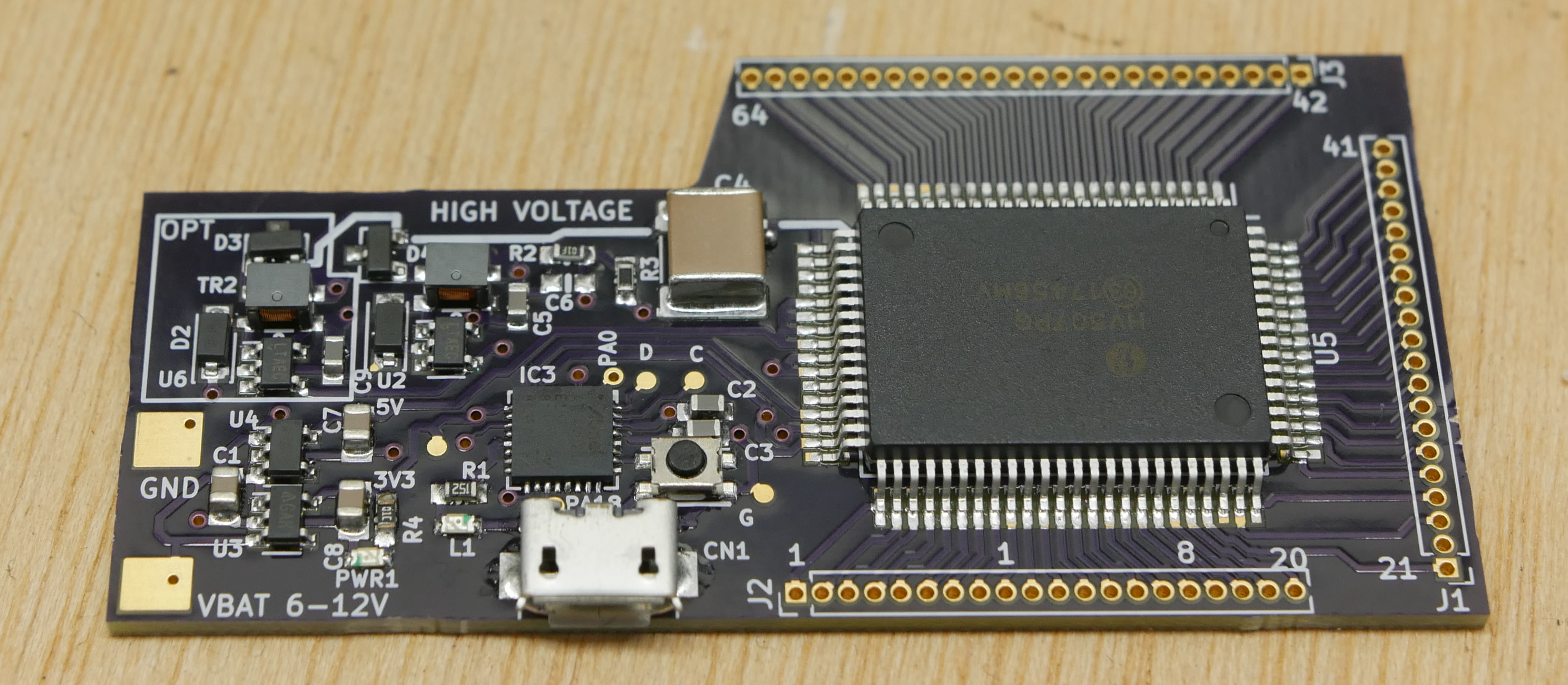 But EL displays are more than just putting a few layers of chemicals on a substrate — you need to drive these displays with high-frequency, high-voltage AC. For this, [Ben] designed a multi-channel electroluminescent driver based on the Adafruit Trinket M0, two LT3468 ICs to generate a high voltage, and either a an HV507 or HV513 to drive 8 or 64 channels.
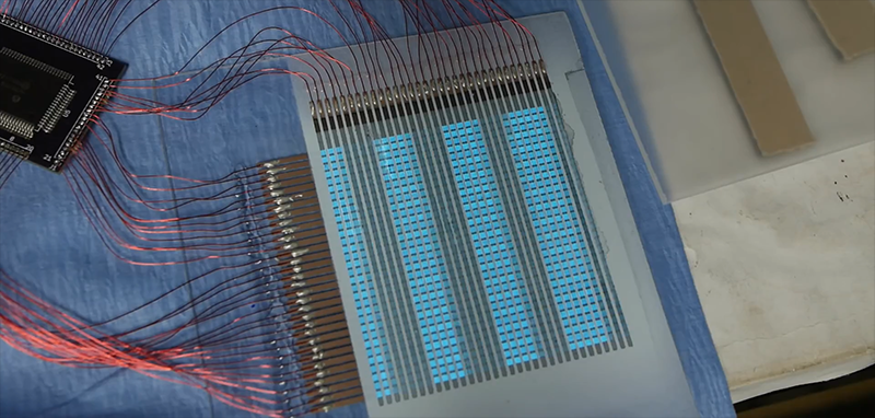
With the ability to create EL displays and drive 64 channels, there really was only one thing to do: a 32×32 display. Even seeing a few lines scan across a 32×32 EL display is magical, but it’s got another trick up its sleeve: it also plays a low-resolution video of Never Gonna Give You Up.
This isn’t a video to be missed, check it out below.


have you seen the price of the material ? 700+ euros for 120 milliliters
Whoa, thats steep.
But I think you get quite a bit of EL out of 120ml.
I don.t konw where you have check the price but is not 700euro.The price is cheaper than that .Tel me from where are you and y wil tel you from where u can buy it and at what price..By the way it worth every money.Lumilor is magic.I work with it on diferent projects (cars,moto etc) and it is wow.
Back in the late 60’s, we developed an inverter designed to light 2″ wide x 4′ long EL flexible strips that were to be used for emergency helicopter landings sites in Vietnam. The were SCR oscillators with an output of 400 hz. The green light was supposed to be especially visible to normal eyes. The engineer who designed the oscillator was very enamored of SCRs, using them everywhere, even when other options were better and cheaper.
This is freaking awesome! If only the stuff would be cheaper I’d get my bike redone…
Rolls indeed. :) A very interesting and informative project. Until the price of the start kit comes down, I’ll have to stick to stitching/hot gluing EL wires onto things.
I always wondered about the prevalence of the whole “roll your own” phrase. Is the community just full of hand-rolled cigarette aficionados or something?
Maybe thats an age-thing. I remember the days when smoking wasn’t that dangerous and there were tobacco-commercials everywhere. One subway-ride and you saw twenty billboards with at least five for hand-rolling tobacco. Hence “roll your own”…
Could be plausible?
Small aside: it’s not as if smoking was inherently any more safe/less dangerous in the past vs now, it’s just that social perception has changed and there are more publicly available statistical data from case studies now vs then.
Back on topic: I wonder what the venn diagram for smokers and makers/hackers looks like since “roll your own” is such a common saying in our arena.
Why are people taking it so literally? It’s an anachronistic metaphor. “There’s more than one way to skin a cat” doesn’t necessitate that I have experience skinning cats. It’s just pedantry…
Well, I and my daughter know that “flying by the seat of your pants” and “slippery as an eel” are literally true.
How’s the daylight viewability? Any better than OLED?
I would hazard a guess that it is worse, since the contrast between the unlit regions and the lit regions for these el displays doesn’t seem great. Also many of the el panels/strips/wires I have seen tend to look fairly dim until you turn off the lights and let your eyes adjust.
Super fun but not long lasting. EL stuff is best case a couple thousand hours life to 50% brightness. That’s less than a year if you have it on 8 hours/day. If it’s not sealed from humidity or if you drive it hard to make it bright – you reduce the usable life even more. EL is not as long lasting as LEDs, or LCDs, or VF, or gas discharge displays.
That rick-roll-spoiler wasn’t necessary!
Shame on you, hackaday!
No hard feelings, tho.
This is cool, but cost-prohibitive, to say the least.
Wonder if there are common/disposable sources of material that can be hacked to work similarly… Glow-sticks, perhaps? Glow-in-the-dark paint? Scrapings from inside a CRT?
Glowstick? For sure no.
Glow-in-the-dark paint could be similar.
But you need some more layers:
Conductive base: possible
Dielectric: sounds quite easy to apply some insulating lacquer
Transparent conductive top coat: really difficult and/or expensive.
“The Truth” linked to the patent for this process. This mentions “zinc sulfide-based phosphors doped with at least one of copper, manganese”. AFAIK that describes some substances used as glow in the dark pigments.
For the dielectric layer it mentions things like barium titanate and other common dielectrics used for ceramic capacitors. So in theory you could etch away the electrodes of some ceramic disc capacitors and grind them up.
This PEDOT:PSS conductive polymer also costs 167 dollar for 100ml at other sources. This stuff seems to be just that expensive.
I’m just going to leave this right here for anyone that might be interested in how the technology works.
http://patft.uspto.gov/netacgi/nph-Parser?Sect1=PTO2&Sect2=HITOFF&u=%2Fnetahtml%2FPTO%2Fsearch-adv.htm&r=1&p=1&f=G&l=50&d=PTXT&S1=zsinko.INNM.&OS=IN/zsinko&RS=IN/zsinko
I’m impressed with the little heat pad (video 8:20) he’s using to harvest the goodies off that PCB. Any idea what it’s called, and where I can get some?
Maybe a ceramic heating plate, like this. But what wattage/voltage does works well?
Many options:
https://www.aliexpress.com/item/XH-RJ404020-ceramic-heating-tablets-High-temperature-heating-plate-40-40-2mm-12V24V220V/32788212208.html?spm=2114.10010108.1000013.1.b386569cCVMTn3&gps-id=pcDetailBottomMoreThisSeller&scm=1007.13339.99734.0&scm_id=1007.13339.99734.0&scm-url=1007.13339.99734.0&pvid=47a91880-e850-4d75-aa5e-f7931984dde7
You can used use an old clothes iron.
But, then, if you get solder on the iron, don’t use it to make toasted cheese sandwiches!
This is great stuff, although EL has it’s flaws, there’s the benefit of getting flexible displays into the hands of people who like to tinker.
Wonders if this process could be done by a modified inkjet printer or similar for thin traces on the pixel matrix display.
even an RGB set of strips could be applied then, thus making for higher resolution displays. Would be fun and also possibly quite usable in every-day systems.
I guess it could be printed in a laminate sheet, binded and then a layer for touch sensing printed… just as another idea
Very cool project and build, thanks. Are assembled PCAs available? If not, are PCB and BOM files available? Might have an application on which to try this technology.
I wonder how narrow traces of the materials can be made. It would be nice to be able to make a pixel array.
Possibility to make wearable, to be well visible riding bicycle at night?
Or maybe painting for luxurious car!
How come I can not find a 4v electroluminescent controller? I want to use a 18650 battery!
Hi Ben, awesome work! I wanted to ask if you could clear up some questions about the display layout? The first layer are horizontal bars of copper backplane followed by the dielectric and lumicolor layers, are you using the PEDOT:PSS as the vertical bars in the typical passive matrix layout? Do you incorporate bus bars or another copper element for the pixels to maintain contrast?