[Mark Rehorst] has been busy with his Ultra MegaMax Dominator (UMMD) design for a 3D printer, and one of the many things he learned in the process was how not to design a 3D printed belt clamp. In the past, we saw how the UMMD ditched the idea of a lead screw in favor of a belt-driven Z axis, but [Mark] discovered something was amiss when the belts were flopping around a little, as though they had lost tension. Re-tensioning them worked, but only for a few days. It turned out that the belt clamp design he had chosen led to an interesting failure.
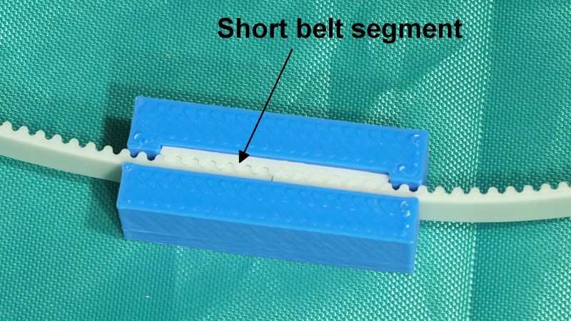
 The belts used were common steel-core polyurethane GT2 belts, and the clamp design uses a short segment of the same belt to lock together both ends, as shown above. It’s a simple and effective design, but one that isn’t sustainable in the longer term.
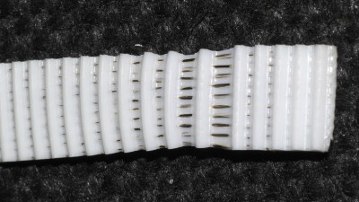
The problem was that this design led to the plastic portion of the belt stretching out and sliding over the internal steel wires. The stretching of the polyurethane is clear in the image shown here, but any belt would have had the same problem in the clamp as it was designed. [Mark] realized it was a much better idea to use a design in which the belts fold over themselves, so the strain is more evenly distributed.
[Mark] has been sharing his experiences and design process when it comes to building 3D printers, so if you’re interested be sure to check out the UMMD and its monstrous 695 mm of Z travel.


Certainly this is an indicator that there’s too much weight hanging on the belt, no?
I agree. Both my delta and replicator two use moulded belt shaped pieces of GRF as belt clamps and they haven’t had this issue, and especially the delta which is under considering jerk hasn’t shown any evidence of this. The clamp area on the delta is about 12 mm long. It IS something i will be checking for in the future though.
The delta is nearly 2 and a half years old, and still no issue.
Not so much the weight as maybe trying to set tension too high. Unfortunately, there is little info on steel core belts on the web and when you use them you’re on your own. The weight is about 3.5 kg being held by two 10mm wide steel core belts. That shouldn’t be anywhere close to the load limit of the belt (when it’s secured in a proper clamp).
Yes, I see. Flat like in the top image, it’s only the plastic part that is being held, but if folded over, the internal cables are constrained as well. Guess I should redesign my belt clamps on my printer.
I’ve already redesigned it and replaced it. You can see it here: https://drmrehorst.blogspot.com/2018/12/another-interesting-3d-printer-failure.html
Is it just added friction you need? I don’t see how this helps except more friction around the posts. A way to strip a bit, like insulation from a wire, and bind the steel seems like the solution. Or belts made with stranded cable or with regularities like rebar so there is a grip for the plastic that forms the teeth.
I would suggest copying the design from the Prusa MK3 which has teeth in the printed piece that engage with the belt. It’s extremely strong and easier to use than the round type. And the files are available online, I’ve personally modified the STL for the y holder in Fusion 360 to fit my printer quite successfully.
You can get these really cheap from stock drive.
This type of stretching failure (and other issues) is why these steel-belted poly belts are shunned in the 3D printing community in favor of the exceptional Gates PowerGrip (or similar knockoff) belts.
I don’t get why cut steel belts are even used at all. The steel in steel belts is intend to constrain the diameter of a complete belt (not cut). Steel belts are only intended to transfer force in one direction and always have an idler / tensioner on the “slack” side of the belt. The tensioner always applies pressure to the flat side of the belt to provide friction between the steel and polymer across the entire diameter of the belt, not just one small section. The tensioner is usually quite large to increase the surface area of compression between steel and polymer as it passes over the tensioner and is also usually located close to the drive gear.
Steel is smooth and provides poor friction with the belt polymer. To use a cut steel belt you need to provide compression on the belt for a considerable length to create friction between the steel and polymer. Even then you will never get the rated force transfer from the belt.
On the other hand fiberglass belts provide good friction between the fiberglass and polymer and are a far better choice for cut belts.
I really can’t see any advantage of a cut steel belt.
Am I missing something here?
Fiberglass is fine. And here is the optimal belt tightner: two loops with a zip-tie between them.
Here’s an old Prusa with that mostly implemented, circa 2011.
https://i.imgur.com/0Tx12lc.jpg
It still runs on the same 7-year-old zipties. I’ve only clicked it up once or twice in the intervening time.
Tension is good, but too much tension isn’t.
It’s definitely a quick and cheap way to do it!
I have been unable to find much information on steel core belts, even basic stuff like minimum bend radius, on the web. What is your source for this info?
The Gates website is a good start.
Or google
https://www.google.com/search?q=sychonious+bely+product+selector
Kevlar is more often used than steel now.
Synchronous belts are extensively used in small machinery.
Have a look at clamps and you will see that there designed to put a lot of compression on belts.
A floating wedge compression system might work better for what you want.
What you’re missing is the whole reason I chose steel core belts in the first place- minimal stretch. I loaded the bed with about 4 kg of filament today and measured the stretch of the 9mm wide glass core belts that replaced the steel core belts. The glass core Gates belts stretch, about 150 um/kg, more than 3x as much as the 42 um/kg stretch of the 10mm steel core belt.
I’ll be putting steel core belts back into the machine, with a better belt clamp, of course.
I think the “other issues” are the main reason they aren’t used. Other issues including unknown minimum bending radius. Most people who try to use steel core belts use pulleys that are much too small which causes early failure of the steel wires in the core. Then the belt stretches over the broken steel wires, similar to the way it stretched in my belt clamp.
Power transference is a function (product) of belt strength and belt speed. Lager pulleys slow the belt and reduce power transference. Smaller pulleys increase reinforcement fatigue especially with steel, That’s why Kevlar is common now.
There are online tool so optimize these things.
What your doing will work best with a compression lock of reasonable surface area. Though you might want to try Kevlar.