Watchdog timers are an often overlooked feature of microcontrollers. They function as failsafes to reset the device in case of a software failure. If your code somehow ends up in an infinite loop, the watchdog will trigger. This is a necessity for safety critical devices. If the firmware in a pacemaker or a aircraft’s avionics system gets stuck, it isn’t going to end well.
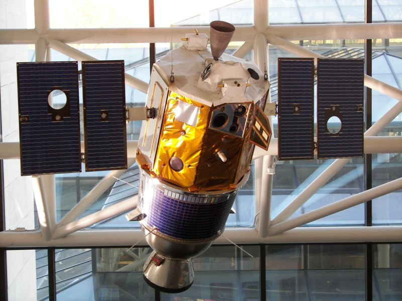
In this oldie-but-goodie, [Jack Ganssle] provides us with a great write up on watchdog timers. This tells the story of a failed Clementine spacecraft mission that could have been saved by a watchdog, and elaborates on the design and implementation of watchdog techniques.
If you’re designing a device that needs to be able to handle unexpected failures, this article is definitely worth a read. [Jack] explains a lot of traps of using these devices, including why internal watchdogs can’t always be trusted and what features make for a great watchdog.
Thanks to [Jan] for the tip!


“… including why internal watchdogs can’t always be trusted …”, Quis custodiet ipsos custodes?
I was thinking about this too. I like the “two controllers watching each other” approach discussed in the blog post… but what if they both fail at the same time for a shared reason?
then there are bigger problem afoot then a simple rest can fix,
Use two different controllers so the blocking conditions won’t be the same for all.
But redundant system should have at least 3 devices, so use 3 different controllers to watch each other.
what if that fail?
https://mfas3.s3.amazonaws.com/styles/grid-3_thumbnail_retina/s3/MinorityReportSFW_0.jpg
Reminds me of logic with automation and some not liking logic and automation, even if with redundancy to create oversight human review positions that are still required for the logical automation systems maintenance at the least, that prevent human data entry transaction and whatever determinate errors found when investigating the system. The challenge of coming from paper based or even hearsay systems to automation of transactions in the simpleton world. Some can’t afford the redundancy, some can afford the redundancy, some like indeterminate/undetermined errors and hate the CAPA investigator even with creative fail safe mechanisms to make everyone not look bad.
The Boeing 787 has to be powered down then re-powered every 248 days or it crashes, both literally and figuratively because of what may be a simple integer overflow. Where is your watchdog now?
https://www.i-programmer.info/news/149-security/8548-reboot-your-dreamliner-every-248-days-to-avoid-integer-overflow.html
Overflows in timers are very easily corrected when calculating time intervals by subtracting 2 timestamps.
You can easily confirm this with pen and paper. Take as example an 4 bit integer, and draw the numbers in a circle, just like a clock. Then calculate some intervals by subtracting timestamps, and you will see that the interval will be calculated correctly even when the integer overflows between the timestamps.
Because of this I almost always use 16 bit timer variables, because those are big enough to handle the time intervals I’m interested in, and they use less space & execution time.
I’m not sure where I learned this. It might well have been one of Jack Ganssle’s articles. His pdf on debouncing, with scope pictures of different kind of switches, is also a very informative read.
Not sure to understand:
T1 0 –>–7–>–15
T2 3–>-10–>—2
T2-T1 3–>–3–>—13
Even if there is a distance of 3 on your circle, the last delta is wrong because only one timer (T2) overflow not the first one (T1) i.e. you send something at T1 and you get an answer at T2.
so it’s not alway wrong but not always right.
Paul is actually correct, as long as you consider all your timestamps as unsigned numbers, and always compare ‘durations’ (i.e. difference between two timestamps) and dont try to compare instances, e.g. if (t1 > t0). This is due to the Modular Arithmetic of unsigned integers.
Example (stolen from https://arduino.stackexchange.com/questions/12587/how-can-i-handle-the-millis-rollover ) :
So lets say previousMillis is 4,294,967,290 (5 ms before rollover), and currentMillis is 10 (10ms after rollover). Then currentMillis – previousMillis is actual 16 (not -4,294,967,280) since the result will be calculated as an unsigned long (which can’t be negative, so itself will roll around). You can check this simply by:
Serial.println( ( unsigned long ) ( 10 – 4294967290 ) ); // 16
Nice read indeed.
It is worth noting that from my experience, radiation induced SEEs can interfere with the Device Service Unit (or however the manufacturer calls the external RESET handling unit), resulting to a system unrecoverable even using an external watchdog connected to the reset.
To overcome this, instead of issuing a reset the watchdog can be connected with a MOSFET to the power line of the μC effectively power cycling on timeout. Combined with a bit of additional circuitry, this can also be used for latchup protection.
A career in electronic security brought a lot of experience with watchdog timers. These equipments are intended to operate for long periods without attention.
My favourite was a simple oscillator constructed from a schmitt inverter, resistor and capacitor that would free-run unless it was hit periodically with a pulse from an AC coupled output pin. The output of the inverter was connected to the processor reset pin and provided the initial start-up reset. This was almost unbreakable so long as the timeout was set to allow the crystal to start oscillating (this can take tens of milliseconds on microprocessors in my experience).
When the processor was reset it would generate (say) 16 pulses to ensure the watchdog was fully awake then continue with program initialisation. The main software loop generates a single pulse per cycle to kick the watchdog* and keep it awake. It is important that this reset was not in an interrupt handler as it has been known for interrupts to continue running even when the processor has run wild.
If a particular process has a long duration such as reading a serial EEPROM then the watchdog can be kicked periodically within the process, but this must be an exceptional condition. Alternatively the processor can reset itself by just suppressing the output pulses.
Thousands of these were in service and some are still active; I have seen at least two of my designs incorporating this class of watchdog during the last six months.
[*] No animals were harmed in the performance of this function.
schmitt inverter ….. read ‘555 timer’ ?????
A single transistor, capacitor, resistor and diode is a lot less prone to failure.
> … ‘555 timer’ …
That should read:
> … ‘555 timer’ …
Shudder!
Was there a name for these circuits? Band name or other wise?
Which circuits? The watchdog, the equipment it was installed in or something else?
You said thousands of these were in service and some are still active, in reference to the watch dog circuit. I thought maybe it was a component or development board version I could order and study.
They were integrated into the designs of various obsolete electronic security equipments, mainly alarm control panels. Later processors incorporated watchdog timers so the external circuit was no longer required. If I can find a circuit I’ll put it up here.
Something I read about rather than experience myself was a system where a continuously resetting watch dog cause the CPU active LED to appear to be flashing as normal,. My solution : at startup, keep the cpu LED on solidly for a second or two before entering the ever popular once a second flash. Indicator philosophy can be interesting, ideas like the dark cockpit etc. To enforce my own consistency I put my philosophy on the modern version of paper… a Web page. found here… http://opend.co.za/tutorials/indicator_concepts/index.html
His mailing list has been discussing watchdogs for the last month see http://www.ganssle.com/tem/tem364.html and http://www.ganssle.com/tem/tem365.html
An actual watchdog timer going off in a station sign board (Bristol Parkway station):
https://www.flickr.com/photos/anachrocomputer/25505384655
I can just picture people in the station looking around nervously for a watch dog.