For those outside the rocking and rolling of California’s tectonic plate, earthquakes probably don’t come up on a daily basis as a topic of conversation. Regardless, the instrument to measure them is called a seismometer, and it’s entirely possible to build one yourself. [Bob LeDoux] has shared his article on how to build a Fluid Mass Electrolytic Seismometer, and it’s an impressive piece of work.
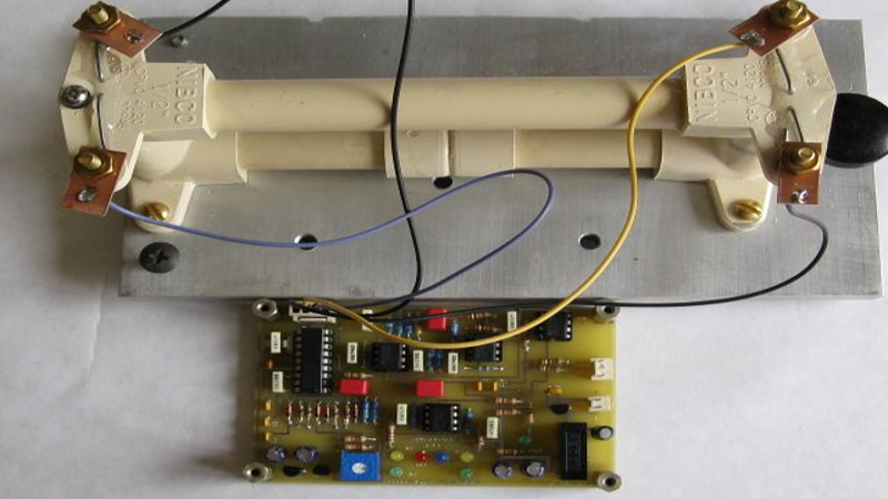
This is an instrument which works very differently from the typical needle-and-graph type seen in the movies. Fluid is held in a sealed chamber, with a restricted orifice in the center of a tube. The fluid level is monitored at each side of the orifice. When motion occurs, fluid levels change at either side which allows seismic activity to be measured.
Hooked up to some basic analog electronics, in this form, the device only shows instantaneous activity. However, it would be trivial for the skilled maker to hook this up to a datalogging setup to enable measurements to be plotted and stored. The entire project can be built with simple hand tools and a basic PCB, making it highly accessible.
It’s not the first time we’ve seen a seismometer, either – the Raspberry Shake project is a distributed network of sensors running on the Raspberry Pi.


Interesting idea. I’m glad that report includes a bunch of references — it’s pretty thin on theory of operation and explanation of the circuit. They must have iterated on that orifice diameter quite a bit: it seems like it would have a large bearing on the frequency response of this thing.
It reminds me a lot of Charles Wenzel’s “water hammer” seismometer: http://www.techlib.com/area_50/waterhammer.htm where he chose not to let the fluid slosh back and forth and measure its level, but rather measure the pressure head of it instead. Rather elegant and simple, I thought. (for the time and frequency nuts in the crowd, yes it’s THAT wenzel.com Wenzel, but you probably already knew that)
The parts and PCB look like it was made about 1970 :-) The same circuit could be/is a tilt-meter.
I think with some clever DSP you can calibrate and get ground motion from this. Maybe without the orifice. You can determine the frequency response and phase from an impulse. It will show that the output is proportional to ground motion, velocity, or acceleration depending on frequency. By massaging the data and integrating a couple times you can get pure ground motion versus time. Two of them at right angles can give you a vector in the direction of the displacement and lots of other cool stuff.
Yes, the seismometer is a step back in time. I had given up through hole construction years ago. But with critical noise and dynamic range requirements I decided to use the existing circuit layout. Seismic experimentation is a wide open field that could use some new blood. They are still using classic op amps to extend down the sensing frequencies to .01Hz. More options are needed for 24 bit or higher analog to digital converters.
I’d like to see a new group interested in pursuing the opportunities in seismology.
I’m in for a group. I have built traditional systems since, well, just say I have recordings leading up to and including Mt. St. Helens blowing up. I have a portable but very heavy USGS standard seismometer and some 24 bit ADCs and low noise op-amps. My intention is to see how little gain I need along with the ADC and then over-sample as much as possible and do everything digitally to cover from 10Hz down to zero.
Also fiddling with the arm and coil + magnets from a hard drive. Strength of modern magnets means I might get by with far fewer turns of a coil. Maybe some 3D Printed structure.
Look into building chopper stabilized preamps. It is an old technology but still has it’s used in places where you are working with low frequencies and want zero long term drift, I like your ideas of using more modern magnets but I have some concern that they may have an effect on the damping of the system, Another approach that may be interesting would be a long lever on the tail end of the moving mass to amplify motion and an optical quadrature type detector, skipping the analog stages altogether.
You can buy ready made chopper stabilized OpAmps/Instrumentation Amps (“zero drift”) from TI or analog devices.
You shouldn’t need them. Especially at these frequencies. We did gain of 1,000,000 in the 70’s with a pair uA741 as high gain low pass of 1000 each. With 24 bit ADC (at 1.8V P-P that is 0.21uV resolution. Some anti-alias filtering first is good, so add a gain of 10 or 100 with a low pass filter and you are in the 1nV range, and yes, there will be noise but I think way below any interesting signals.
That old system based on uA741’s had a 4000 turn coil of #40 about 6x5cm and what amounted to OK magnets from the 1960’s. I have a feeling you could use 100 turns and a large diameter modern rare-earth magnet and be in great shape.
I was thinking the same. Wondering about reaction time vs pipe size specifications for optimal tuning. Similar to the induction or piezoelectric devices with a tuned mechanical resonator rod/ball.
I’m so at the through hole stage of my skills… with some surface mount capabilities (mostly practice salvaging components). This is a neat, well detailed and like even noted… developable… novel to me design.
Once you have the response to a set function or an impulse, you can find all the frequency response. Which means you can “undo” the frequency dependence to see what motion caused it.
Hmm… if through hole components and PVC pipe is all you need to bring you back to the 70’s then I think you are under estimating the efforts made here. May I remind you that many projects on hackaday use the same components but are pushed only into a wonky breadboard (sometimes hidden in a hideous 3D printed case), while this project is made on a nice PCB. And it is even nicely documented. This is more then I can say of many other project here. If this method of working reminds you of the 70’s, then I hope we get a retro revival on hackaday soon, cause I like it!
Though, I have to admit, I do like SMD, it’s space efficient, the shorter tracks can result is less noise in the overall circuit in some ways easier to mass produce. But hey, when a project works and works reliably, does it really care how it is made? Regarding my own projects, I mostly solder them onto prototyping board, ordering a PCB most of the times isn’t worth the money and long wait most of the times, good is good enough.
I think it’s mostly the brownish, off-white color of the pipes, which reminds of the 70ies. But also in the 70ies good electronics was designed, often longer lasting than today’s cost optimized stuff. So I would not take the comment offensive.
The original documents can be found here:
https://groups.google.com/forum/#!topic/psnlist/ih4p__5cGW0
This is about as ridiculous as it gets. Fluid flow through an orifice is a *very* difficult problem. Yes, this will indicate horizontal motion to some degree. But as a seismograph it is utterly useless.
Those needle and drum things are *not* seismographs. They are the data recording instruments which this thing does not have.
There is a vast literature on seismograph construction. Why anyone would ignore that to build this is completely beyond me. Amateurs can and have built instruments which equaled the performance of professional instruments. That’s actually an interesting project. This is a joke.
BTW I’m a retired PhD level seismologist. There is *no* amount of DSP that could turn this into a usable instrument. To do that you’d have to solve fluid flow through an orifice to much better precision than current practice.
Doubtless Elliot will delete this for being “negative”. But the facts don’t change if he does.
Dave Nelson, the instrument designer, is a retired aerospace engineer with a specialty in instrumentation. He spent ten years developing this sensor. His seismic bunker contains professional instruments. The proof is in the pudding. The output of the plastic sensor closely matches the professional instruments.
The document links include a multi-page spreadsheet by Brett Nordgren which includes an analysis of the fluid flow through the orifice integrator. Brett also developed an LTspice model that links the sensor action through the circuit board.
I have added additional files to the PSN Google group:
It is a single sided board, intended for for toner transfer, or similar technique. The board screws to the top of the instrument. The schematic is unchanged except for size and new mount points.
The board passes all computer tests but I haven’t yet built it.
@ Reg:
It _would_ be swell if you offered constructive links, pointers on how it can be improved, etc. Simply a “this isn’t good” without being helpful is, ummm, unhelpful.
But the other thing is hubris. Taking such an extreme stand (“utterly useless” and “is a joke”) open you up to strong and embarrasing counter-argument. And if I were a betting man, that’s where I’d put my money on this one…
But yeah. You got it right. I wish that you’d moderated your tone a little bit: be nice.
Note I said DSP without the diaphragm. And I think you mean seismometer, not seismograph. Anyway, as long as you can linearize response for small displacements, you can attack with standard DSP, otherwise you have to go non-linear. But at common small processor speeds, iteration on non-linear solutions is just not a big deal, especially at 100Hz sample rate. Then again, I have yet to meet a seismologist who is not lost if you move off the old equations of coupled seismometer and seismograph motor – well, except one – but he was a theoretical physicist who liked geophysics and quite brilliant.
i like the idea of using the pressure sensor, but in this bridge type configuration, so as to be dual acting.
take this structure, no orifice in the bottom part, but a dead stop in the middle of the top part. have a pressure sensor on either side, acting as a bridge since the water couples them tightly.
nice project. well executed.
Excellent! Now all I have to do is build a rocket to take it to Mars to give those smug InSight engineers a run for their money.
My four foot tall spring reverb went off twice during 2 events. It does not rattle when I walk or dance. I used to leave the living room studio stuff on all the time. I heard it first as I woke up. New Madrid and Wabash faults at fault. Indiana!
Pendulum weights are a good standby. We used to have two train tracks 4 blocks away in town. One night I noticed a alligator clip lead hanging from it’s end jumping up and down in a rhythm, I sat still it jiggled away then I noticed that there was a freight barely discernible. It quit when the train was gone. Resonant things can be very sensitive but only near or at frequency.
Interesting project. Are the Gerber files for the PCB available?
The link to the original documents, above, include schematic and PCB files for ExpressPCB. There is software and there are vendors that can convert to Gerber.
I am also developing a single sided board for toner transfer. This board mounts between the contact screws on top of the sensor.
Hi Bob,
I’m struggling to find any of the documentation, has it been moved ?
Nick
Nice project. I had one thing that stuck in my head after reading your fine write-up- its almost off topic but stuck. Why is CPVC plumbing required? Is there something about PVC that makes it unsuitable for this? Thanks for sharing.
The flanged elbows aren’t available in PVC.
Someone had a look at Linear Technology Application note #43, hm ?