Recently, I was lucky enough to receive a big haul of retro computer gear from a friend who was emptying out his garage. Even better, the haul was almost entirely old Amiga gear — my favorite computing platform of all time. Upon returning home, I gleefully sorted through the boxes, powering things up one by one. Amazingly, everything worked… except for one lonely Amiga 500+. I was greeted by a dull grey screen. This wouldn’t do, so naturally, I got to work.
It seemed like a shame to be opening the machine, as after almost 30 years of life, this one still had its warranty seal intact. Regardless, nothing ventured, nothing gained – the Torx bits were at hand and the screws were coming out.
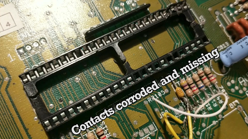
Inside, I found much what I’d expected. The electrolytic capacitors were all clean and holding up well, but there was significant corrosion caused by the clock battery. It was thankfully localised to a small cluster of traces near the Gary chip, which provides glue logic and floppy drive functionality. Looking closer, I also noticed that Gary himself was looking rather corroded. Commodore were kind enough to socket the custom chips on all Amiga boards, so I popped it out – only to find that several contacts in the socket had broken or corroded away.
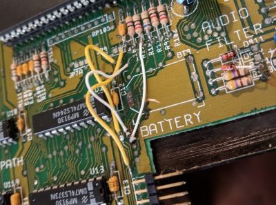
The job was looking like a frustrating, yet achievable one. I cut the battery off, then began patching the traces. One by one, I traced out where they were supposed to go, then scraped back a small amount of soldermask in order to have copper to solder to. Then, a thin patch wire was tacked in place to restore the connection, before verification with the multimeter.
Fixing the Gary situation was going to be more difficult. The entire socket would have to be removed. I cut the socket away pin by pin, so I could deal with each one individually. Patience is the name of the game here, as being too rough in removal can lead to damaged vias or traces. I used a spring-loaded solder sucker to remove as much of the solder as possible from each pin, and then heated the via once more while pushing the remains of the pin out with a toothpick. I found this technique to be relatively successful, far more so than former attempts using metal wire as a pusher. The hardest pins are always those with connection to the ground plane – there are no thermal reliefs, so the solder sucker doesn’t work particularly well there. With perseverance, I was able to remove all the old pins, and solder in a fresh socket for Gary. At this point, I felt accomplished. I’d solved the obvious problems on the board, and thus would clearly be rewarded with a working machine.
Alas, it is rarely so simple. Upon powering up the machine, the screen was wavy, lacking any video sync, except to occasionally flash up a solid colour now and then. Blue, red, green – these are all various error codes the Amiga can display. It seemed unlikely I was suffering all of them, but I was unsure what to do next.
After some further research, I’d heard of another Amiga fan who had issues with the extended RAM present on the Amiga 500+. Using jumper settings, they were able to disable the extra RAM and get the machine to boot. As this seemed easy and didn’t involve serious work on my part, I gave it a try – to no avail. I was rather petulant that my blind stab in the dark didn’t work, and set the machine aside for a week while I brooded over my next move.
Organ Donors
A friend then suggested, given that I had a working Amiga 500, to swap over the custom chips in order to identify if any of them in particular are faulty. After some careful work with a flat-bladed screwdriver, and shelling out $15 for a tool to remove the Agnus PLCC from its socket, I eventually figured out that all the custom chips from the 500+ were fine, barring Agnus, which had a version incompatibility between the two machines.
At this point, I was at a loss. I was losing faith in the machine, and was reticent to spend hours blindly probing around for more broken traces when the board looked, for all intents and purposes, fine. It was then that a gift miraculously appeared before me – the Amiga 500 Troubleshooter, courtesy of fellow countryman Ian Perry. It’s a table which shows which areas of the machine should be investigated for given symptoms. I noticed that my wavy screen without sync was likely caused by either a faulty Agnus chip or a failed 74HCT245 in the video output circuit (U41).
I had a hunch that Agnus was fine, so decided to spring for a few 74HCT245s at 90 cents each, plus ten dollars shipping. U41 was not socketed on the motherboard, so it was a case of carefully cutting away the chip pin by pin, before again pushing the remains out with toothpick and soldering iron. As is the custom, I installed a socket before putting in the fresh chip, just in case.
With bated breath, I powered the machine up, connected to the classic Commodore 1084S monitor. The screen was clear and synchronized, but grey… before turning a shade of blue. It continued to do this in a regular cycle. While the machine was still non-functional, my confidence was buoyed. The Amiga was now behaving consistently and showing just one error message – the blue screen representing an issue with one of the custom chips – Agnus, Gary, or Denise.
It was at this point that my luck came home. While sitting there, quietly proud that I was getting closer to a solution, I keyed in “Amiga 500 Plus blue screen” into the search bar. The first result was an eight-minute video that I wasn’t quite in the mood for, so I decided to check the description. It mentioned offhand a broken trace that was hard to spot with the naked eye, linking pin 4 of Gary to pin 1 of U12. A quick check with the multimeter showed no connection on both my working and broken machines, but my interest was piqued, so I decided to look up a schematic.
Finding the service manual on archive.org, it was clear that pin 4 of Gary goes to resistor R113, which then goes to pin 1 of U12, a 74LS244. Checking my machines again, the working Amiga 500 had the connection, while the 500+ did not. Suddenly I found myself rather excited, and hurriedly soldered in a patch wire from Gary to the resistor in question.
The tension was palpable as I plugged in the machine, and flipped the power supply on. There was a grey screen, followed by a new sound – a few clicks from the floppy drive, before the glorious sight of the 2.0 ROM Insert Disk screen sprang forth. I had finally done it!
I was rather ecstatic, for having attempted to fix many retro machines over the years, this was the first one that had been at once both completely successful and without causing any major collateral damage to the machine in the process. Plus, I now had a hotrod Amiga 500+ as a part of my small collection.
The process could certainly have been quicker if I wasn’t so reticent to do the hard yards and check more connections on the PCB, but the biggest help was definitely the troubleshooting matrix. It’s an incredibly useful tool that boils down years of experience into a quick reference guide.
Overall, the repair was a win, and I’m looking forward to firing up some Lemmings before hooking up a couple machines over serial for a multiplayer game of Stunt Car Racer. Most enjoyable!


Damn. Now I have to see if my 500 will boot after 20 years on the floor of my computer room.
I’m not sure I knew that it had s battery. So much “early” equipment didn’t, I’m sure I’ve been careless about this. My Radio Shack Model 100 no longer starts, I should have opened it long ago, clear out the backup battery if nothing else. I’ve probably let some rot set in on some of the Macs.
Michael
The 500 (not 500+) didn’t have a battery on the mainboard, but most of the memory expansions did have the battery.
“The hardest pins are always those with connection to the ground plane – there are no thermal reliefs, so the solder sucker doesn’t work particularly well there.”
I remember when a copper solder wick was sometimes used.
If Amiga used Pb solder, maybe just use an iron at Pb-free settings?
What do you mean “pb-free settings”?
If you have a thermostat iron like the common 40 Watt Weller, you always set it to max temperature and leave it there. The sensor is up the handle, not at the tip which is just a hunk of metal, so if you don’t crank it to max you may not be able to melt any solder in the first place. When it says “430 C” it’s just barely able to melt lead free solder, if you hold the tip on the pad for 20 seconds.
That’s actually the most annoying thing about the whole RoHS business. Regular 60/40 solder melts at 182 C, works from well below freezing to boiling without developing tin whiskers or tin pest, is reasonably wetting (spreads/wicks easily) and has a single melting point so it doesn’t care about cooling time considerations. It’s also cheap as dirt.
All the lead-free alternatives compromise one or the other. They’re poorly wetting, with a high melting point and poor mechanical strength, or it turns to dust below freezing, or grows whiskers and shorts things out, or costs $300 per spool because it’s made of bismuth, indium, silver and gold and isn’t available anywhere.
The local hardware store switched to a tin-copper mix that takes 250 C to melt and it’s really meant for car radiator repairs. The local electronics store only sells 99% tin, which gets tin pest AND whiskers, which makes it downright useless for anything real. I tried to look on Digikey for a spool of something proper, but the only proper low-melting alternatives I found were spools of pure indium.
https://www.sparkfun.com/products/9161
and
https://www.newegg.com/Product/Product.aspx?Item=9SIABKW4D90594&Description=solder&cm_re=solder-_-9SIABKW4D90594-_-Product
I will ask the PCB designer about the thermal reliefs,I don’t remember any designs where we didn’t use them.
I just got a response back from the PCB guy that laid that out and he said he held a blank up to the light and yup, no thermals. He said that they started with thermals on just connectors. Adding what I know about the Commodore attitude back then is we would have been more focused on soldering them into the board then taking them out, and the wave/drag solder process didn’t care about thermals, only people did. Connectors were sometimes post solder assembly which means assemblers would install them manually which would be why we started there with thermals.
It was all kind of new as far as these kind of qtys back then, at least to us. We once had to throw a batch of boards away because no-one stored the surface mount chips in a dry or mothballed area and the leads tarnished screwing up the soldering just enough.
Awesome to hear from someone actually there! Thanks for the info :D
Also, I guess, since it’s a chip socket, you’d think nobody would care because they’d just pop the chip out of the socket.
The company I worked for in NZ was the repair agent for Commodore, we only ever used wick for desoldering as we found that the spring loaded suckers would sometimes pull the tracks. The most common issue I had to deal with was replacing the FDD controller chip. if you connect the drive while the machine is turned on there was a high chance that it would pop. In addition we used to align the heads of drives.
Hi Boris,
I’m very interested in floppy head alignment on these machines. How was it done?
I had a friend who tackled it. He literally just nudged the head, locked it down, tried to run Dcopy, and just kept adjusting it until it worked cleanly. Took 5 hours.
Would love to know how the pros did it!
From memory, technicians here used a “pattern” floppy. Then they would run it, and use a oscilloscope to watch the signals in one or two (marked) points in the board. Then they would adjust the positioning mechanism of the head until the waveforms corresponded to those in the manual.
Ah, so similar to camcorders then. Would be cool to find some documents and see if a pattern floppy could be recreated.
Did you rinse/neutralise the battery electrolyte off the board? If not, you should do that. Vinegar is recommended.
Yeah, sure did. Good tip.
Shame on you for not using proper 30 gauge teflon wire wrap wire for your fixes! ;)
OK, now that that’s off my chest, a hearty “Well done!”
I think you will find, for removing chip/socket pins a pair of fine pointed stainless steel surgical tweezers can often be helpful. I always fear pushing on hot PCB as it sometimes softens just a bit in the heat and the through hole plating can be damaged or even pushed through. Solder wick can also be handy for the holes that just won’t empty. But don’t overheat or press too hard.
That should be “blue” 30 gauge teflon wire wrap wire.
Now I feel like trying to fix the Amiga 4000 I bought for my 30th birthday…18 years ago!
I’ve dreamt of Amiga in the 90’s, played with friends’ ones but I had…an Atari…and not enough money left for an Amiga.
A couple of years ago at the VCF East one of the guys from Guru Meditation was doing a class on repair the Amiga 4000 so I went outside and got the designer of the 4000 who just happened to have stopped by. Jump to 0:55 for when I interrupt him with the news about who was standing next to me… most fun I ever had at a VCF.
https://www.youtube.com/watch?v=SoGFFXbpsfI
That was great!
Thanks!
The engineer on the 500 George Robbins (aka GRR) passed away about 20 years ago sadly.
I wish more people could experience happy deaths…
Yeah I phrased that awkwardly.
Sometimes adding more solder + a somewhat stronger soldering tool helps a lot to remove ground pins.
The extra melted solder provides for the extra hot mass that compensates for the heat dissipated by the ground plane.
And those hollow stainless steel needles also help, sometimes, when you have one that fits the pin and is smaller then the internal diameter of the hole.
Sometimes (often?) we resort to having a big hot tip on one side of the PCB and a solder vacuum on the opposite side.
That is the method that I have found most successful. It saves lots of time, since it both pulls out the pin remnants and cleans the hole nicely at the same time.
The only thing that makes it difficult is lacking proper tools to support the board vertically.
Regarding this fix, I don’t like the look of those patch wires. My preference is to take cut-off component leads and bend them in the same shape of the traces that are being repaired. For longer traces (ie, cases where you’re essentially replacing the trace from end-point to end-point) 30-gauge wire-wrap wire is useful.
agree
I really need to fix my 2000
Check the inside of the plastic case, and see if the guys have signed it. A few of the 500’s had the guys signatures in them.
this then became a thing and they were included in the 1000 and other machines later on. I think the dog also had a paw print in there.
Well done on the repair.
“this then became a thing and they were included in the 1000 ”
The 1000 came first so you have the 500 and 1000 backwards.
AmigaOS 2.0? You do realize OS 3.1.4 was released just before Christmas?
#supportthecommunity
I have a 1000 and a 2000 sitting in my closet wonder if they will fire up.
Old machines always involve a big mixed bag of emotions! So glad you got it up and running in the end, those moments are what make all the pain worth while.