If you’re not familiar with the 555 timer, suffice it to say that this versatile integrated circuit is probably the most successful ever designed, and has been used in countless designs, many of which fall very far afield from the original intent. From its introduction, the legendary 555 has found favor both with professional designers and hobbyists, and continues to be used in designs from both camps. New versions of the IC are still being cranked out, and discrete versions are built for fun, a temptation I just couldn’t resist after starting this article.
If you think all 555s are the same, think again. Today, a number of manufacturers continue to produce the 555 in the original bipolar formulation as well as lower-power CMOS. While the metal can version is no longer available, the DIP-8 is still around, as are new surface-mount packages all the way down to the chip-scale. Some vendors have also started making simplified variants to reduce the pinout. Finally, you can assemble your own version from a few parts if you need something the commercial offerings won’t do, or just want a fun weekend project. In my case, I came up with what is probably the fastest 555-alike around, although I spared little expense in doing so.
Follow along for a tour of the current state of the 555, and maybe get inspired to design something entirely new with this most versatile of parts.
What’s In the Box?
The first 555 timers, the NE555V/SE555T from Signetics, were produced more than 47 years ago. Designed by Hans Camenzind, this part eventually sold over a billion units per year, and has been used in everything from children’s toys to spacecraft; the original bipolar-technology 555 didn’t need radiation hardening, only very rigorous testing, for space qualification. Hans sadly passed away in 2012, but you can hear some audio clips of him discussing the 555 at the Transistor Museum site. In that interview, he relates how Signetics chose not to patent the design. At that time, Silicon Valley enjoyed a culture of mutually assured destruction with respect to intellectual property: companies freely stole ideas from each other, secure in the knowledge that the first to file a patent suit would be hit with an overwhelming response to all of their own infringements. This environment allowed versions of the 555 to be sourced by multiple vendors, keeping prices low and increasing the part’s appeal to designers.
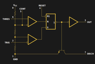 The Art of Electronics called the 555 a kit of parts, and that’s probably the best overall description you can come up with. Inside, you’ll find a voltage divider producing references at 1/3 and 2/3 of the supply voltage. One of two comparators fires when the voltage on the TRIGger pin is less than the lower reference or that on the THREShold pin is greater than the upper one. The outputs of the comparators lead into a digital latch, which can also be reset with an external active-low signal. Finally, the output from the latch drives the OUTput and DISCHarge pins, the latter typically being used to discharge an external capacitor during the high part of the output cycle.
What can you do with these parts? Perhaps the most common use is as an astable multivibrator or RC relaxation oscillator. In this role, an external resistor and capacitor set the time constant for oscillation. Although the original bipolar design had difficulty generating output pulses down to 50% duty cycle, the CMOS variants can handle this by using a single resistor from the output back to the capacitor. While you can make a similar relaxation oscillator from nothing more than a Schmitt-trigger (ST) inverter, the resulting frequency accuracy will be poor, since the hysteresis level on ST inputs is not very well controlled: the timing will vary from part-to-part. By using the voltage divider and window comparator structure of the 555, you get better frequency accuracy and stability, as well as a lot of design flexibility.
The 555 isn’t just an oscillator, though. It can also be used in monostable (one-shot) mode, producing a fixed output pulse width in response to a low-going signal on the TRIGger input. In this mode, applying a voltage to the CONTrol pin allows you to modulate the output pulse width. I’m surprised how often this is used: in just the past week, I’ve heard from two people who’ve found 555s used for PWM dimming of LEDs in commercial products. Beyond the basics, the 555 can be used for timing sequence generators, pulse position modulation, time delays, ramp generators with the addition of a current source, and a multitude of other applications.
Just because it’s so often used does not mean that the 555 is universally loved. An EDN column from 2011 shares some hard-earned lessons in 555 failures and the fact that an analog legend, Bob Pease, was not at all a fan of the part. Still, it’s cheap, easy to use, and good enough for many, many applications.
Why Not a Microcontroller?
Given its versatility, there’s little surprise that this IC continues to find use. But, in the age of $0.03 microcontrollers, one has to wonder if the 555 will eventually lose ground. Besides the amazing variety of innovative designs, and hacks, to build on, there are still plenty of reasons to choose this part over a microcontroller solution, including:
- No programming required
- No software bugs
- No NRE (non-recurring engineering) costs for programming and debugging
- No manufacturing time loading code
- Wide supply voltage range
- No flash memory bitrot or soft errors from cosmic rays or voltage spikes
- No hung or stuck software states; no watchdog required
So, once we’ve decided to go with a 555-type circuit, it’s time to have a look around and see what’s available in 2019. While you can still buy the original-recipe bipolar 555 with its 100 kHz frequency limit from several vendors, the new CMOS versions seem to be where the action is. I took a look at two such offerings.
TI LMC555
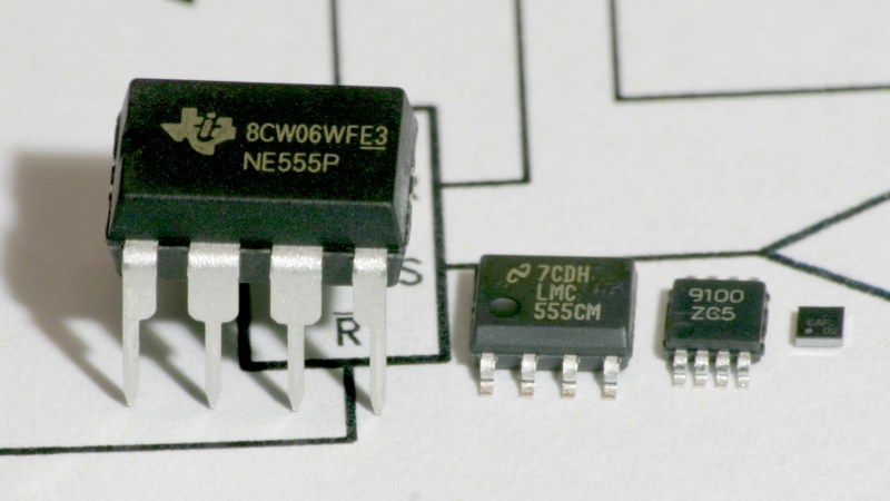
TI’s LMC555 claims to be the smallest and fastest fully-featured 555 available. This is a CMOS variant, with a maximum frequency of 3 MHz according to the datasheet. It’s available in a variety of 8-pin packages, including DIP, SOIC, and VSSSOP, in order of decreasing size.
Also available is the hobbyist’s worst nightmare: a 555 in a chip-sized BGA (ball-grid-array) package. This part is smaller than two 0603 resistors side-by-side. While dead-bugging the DSBGA version would be quite a feat, the existence of such a small package raises a few interesting questions. Where are 555’s this small being used now, and what hacker uses would benefit from this level of miniaturization?
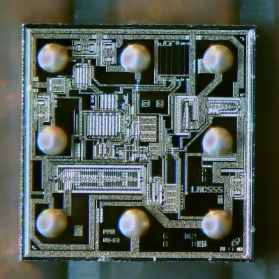
Also note that if you have access to a microscope, you can flip this version on its back and have a look at the die; no strong acids or hacksaws required. You can see the National Semiconductor logo if you look close enough. (TI purchased NS in 2011.)
Microchip “IttyBitty” MIC1555/57
Microchip offers its own version of the 555 concept with the MIC1555/57 timers, both in small but relatively hacker-friendly SOT23-5 packages. The price paid for the smaller footprint is the elimination of a few pins. The MIC1555, which can be used in the traditional oscillator or one-shot roles, is missing the CONTrol voltage input, DISCHarge, and RESET pins. One unfortunate consequence is that PWM applications are out. The MIC1557, on the other hand, combines TRIGger and THRESHold into a single “T/T” pin, and adds a chip select (CS) pin. This version isn’t suited for one-shot operation at all; it’s intended as an oscillator with shutdown (< 1 uA) capability instead. The datasheet lists a maximum 5 MHz astable frequency for either part, which at least on paper, is faster than the LMC555.
Roll Your Own
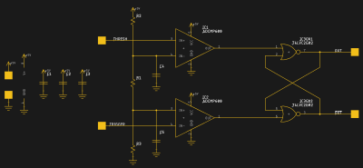 Looking Microchip’s reduced-functionality timer offerings, I wondered what you could do if you built a 555-like circuit from other parts. The idea isn’t entirely new – a 555 built from discrete transistors took one of the prizes in the famed 555 Contest – but the possibilities are pretty intriguing. For my take on the concept, I went for raw speed, choosing a pair of fast ADCMP600 comparators and a latch made from a 74LVC2G02 dual NOR gate. The comparators have a propagation delay of only 3.5 ns, with the NOR gates typically under 2 ns and offering some of the fastest edges I have measured on CMOS logic. Since the RS latch provides two outputs, you can choose either normal or inverted pulses. This also allows one to obtain an output (from the inverted port) without loading the feedback path.
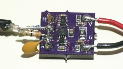
The resulting circuit, which I called the FF555 (see the full project on hackaday.io), was built on a postage-stamp-sized PCB with 50 mil square pads for external connections. I used through-hole resistors and capacitors as the timing components to ease testing. To measure accurate waveforms from the inverting output, I used a 10:1 resistive probe formed from a 1/8 W 453-ohm resistor and a length of RG174 cable. The probe feeds a 50-ohm terminated oscilloscope input.
Testing in astable mode showed that the circuit was pretty robust: it will happily oscillate with no added RC at all. With the output connected directly to the threshold and trigger inputs, it oscillates at 90.5 MHz, this frequency determined mainly by the total propagation delay (~ 5.2 ns) plus some small R and C of the circuit itself. When used with typical RC values, it performs as expected, easily reaching VHF frequencies, with maybe 50 MHz a reasonable limit for repeatability without tweaking for individual spread between units. The output has crisp edges, with the inverting output measuring rise times less than 500 ps, and fall times around 800 ps. (Bipolar NE555’s are typically two orders of magnitude slower at 100 ns.) At these speeds, even short connections need to be treated as transmission lines and terminated correctly to prevent reflections.
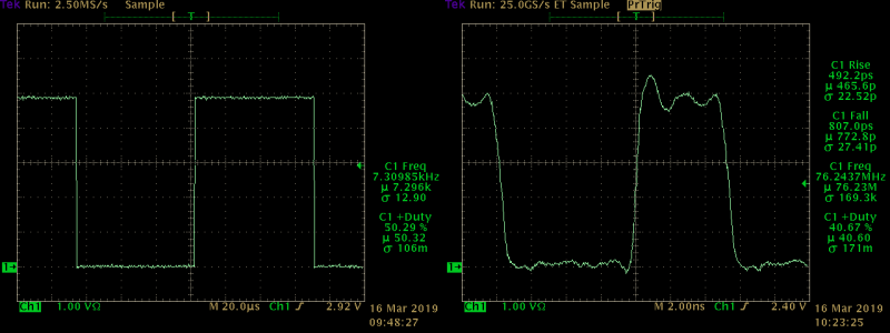
Although using an RC relaxation oscillator at tens of MHz is not a very practical thing to do, using this circuit for very short one-shot pulses or high-frequency PWM might prove interesting. This version also isn’t cost-effective at all: there’s nearly $10 worth of comparators on the board. Even so, I think the takeaway from this experiment is that the architecture of the 555 can easily translate into other circuits if you need something special, or just want to play around in analog-land for a change.
Do these modern takes on the classic timer IC give you any ideas for new applications, or improvements to an existing 555 hack? Can you make a faster one? Let us know in the comments. On the other hand, if you’d like to read more about the 555, have a look at some of the 541 (so close!) articles we’ve run about it over the years.



Iam looking for an retriggerable monostable multivibrator with an pulse width of 500ns any ideas output needs to connect to ground for that time..thanks all
PIC10F320 for example…
74HC123? Depends on how “connected” to ground you need the output to be – you may need an external MOSFET to switch your load to ground for higher currents.
very low current its an IDE PATA pin..thanks for the input
Start with a 74LVC2G14 dual Schmitt inverter. Connect your input signal (a high pulse) to the input of one inverter, then connect a 10k resistor between that node and the second inverter’s input. Connect a 50pF capacitor between the second inverter’s input and GND.
When the input is low, both outputs will be high. When you send the input high, the first inverter’s output will go low, and the second inverter’s output will go low about 500ns later. The width of the pulse is largely independent of the propagation delay through the inverters, since both inverters will have about the same amount of delay (<10ns for LVC logic).
Connect a P-mosfet's source to the second inverter's output, and its gate to the first inverter's output. Connect a 10k resistor between the drain and GND.
When the input is low and both outputs are high, the P-mosfet's Vgs is 0V, so the mosfet will be shut off. Its drain voltage will be 0V.
When the input goes high, the mosfet's gate voltage drops to 0V, turning it on and sending the drain voltage to VCC. 500ns later, the source voltage drops to 0V, pulling the drain voltage and Vgs to 0V again.
By itself, that circuit doesn't retrigger. To add retriggering, put a 50pF cap in parallel with a 10k resistor between the first inverter's input and GND, then connect a diode between the input signal and the first inverter's input. When the input goes high, it will charge the new 50pF cap, holding the first inverter's input high for about 500ns. If the input drops low and goes high again, it will simply recharge the cap, providing retriggering.
The limiting factor on pulse width is the P-mosfet's turn-on/off time.
It will take about 1us for the second inverter's output to go high again after a pulse has ended, since the 50pF delay capacitor has to discharge through its own 10k and the 10k from the retriggering circuit.
That’s a very informative comment. Thank you to explain it step by step.
Analog is not used that much nowadays, and explaining it’s way of thinking is a nice thing.
Thank you for this post. I’ve learned now some new tricks :)
Thanks for your tips will have to give it an go!
Wouldn’t this have a larger footprint, worse timing consistency and worse current consumption than the microprocessor solution while being the same price?
As a student one of my favorite uses for the 555 was as a cheap stepper motor driver. Very old floppy drives used large NEMA23 steppers with a high voltage drive. Pushing 180mA at 12V was enough to control these steppers and within the reach of the NE555. Using 4 555s, this was the cheapest stepper drivers I ever built.
“suffice it to say that this versatile integrated circuit is probably the most successful ever designed”
I’m curious what the competition would be for this title. Define “success” however you want and make your case.
If we can relax the “has to have a constant bit in the part number” I’d suggest the op amp might be in more designs and have shipped more parts?
Yep, Hans Camenzind spoke to exactly this point in the interview linked above:
Q: “Are there other chips with this kind of popularity?”
A: “You could say that the op amp is bigger, but there are so many different op amps, they have to specialize – there is no perfect op amp, so you optimize it, for different parameters. There must be 500 different op amp types.”
When I tried to generate a 1.3 MHz square wave with the LMC555, I got some low frequency amplitude modulation. I had better luck with the TLC555, which also costs half as much. I never heard about the MIC1555, but you just made me order a handful!
A bit of fun – have a look at the 555 with serial interface at https://www.elektormagazine.de/labs/simple-digital-timer
Just wondering if a Schmitt trigger ratio corresponding to the golden ratio ; 1/phi [~.618] and 1-(1/phi) [~.382] could have some significance when used in conjunction with discrete components with values in the same (golden) ratio. Would the circuit behave any different than using 1/3 & 2/3 thresholds
It would be a bit harder to predict the timing.
The 555’s timing is controlled by RC charge/discharge curves, which are exponential. When you charge a cap through a resistor, the voltage across the resistor drops to 1/e of its original value after one RC time constant (literall the value of the resistor times the value of the capacitor). 1/e=0.368, which is reasonably close to 1/3.
If you start with 0V across a capacitor and connect it to a pull-up resistor to VCC, the cap will charge to 2/3 VCC in about one RC time constant. If you start with a cap charged to VCC and connect it to a pull-down resistor to GND, the cap voltage will fall to 1/3 VCC in about one RC time constant.
If you continually charge a cap from 1/3 VCC to 2/3 VCC, then discharge it to 1/3 VCC again, the voltage across the resistor charging the cap changes by 50% either way. It takes about 0.7 RC time constants for that to happen, which makes calculating the frequency fairly easy.
“a culture of mutually assured destruction with respect to intellectual property: companies freely stole ideas from each other, ”
and that is exactly what is required, and why china has caught up (and passed in some things) the USA. The current USA patent system – which is based on lawyers, not innovation, and which they are forcing other countries to follow – is killing competition…
When the system focuses more on what you can stop other people doing, rather that than what you can do yourself, it is broken.
This is an underrated comment. Well put.
in quickly evolving fields, less protection might improve somethings in a 10k feet overview, but take away intellectual property and fields that are much slower get heavily hit as then you spend a bunch in R&D and your competitor just copies the result with no upfront cost, and you don’t have the same time to market advantage (due to being a slower market), that one would still have in the tech space.
The system needs reform for sure, but its really needed.
I’ve been intreagued by these (but not enough to buy any):
A micro-power 555-alike: https://www.jameco.com/z/CSS555-ID-Custom-Silicon-Solutions-CSS555-Micropower-Timer-DIP-8_2146433.html?CID=MERCH
And its cousin with internal timing cap: https://www.jameco.com/z/CSS555C-ID-Custom-Silicon-Solutions-CSS555C-Micropower-Timer-with-Internal-Timing-Capacitor-DIP-8_2146450.html?CID=MERCH
Both also have internal counters, and some level of configuration.
OK, read this article last night, then in class today (1st year EE) was taught all about the comparators inside it and how it all works. Weird coincidence
I could have done it with a 555!
oh, wait…
Hi, you say that the Microchip MIC1555/57 models can’t use used for PWM – of course they can with the right supporting circuitry. I’ve uploaded 4 circuit diagrams to imgbb (here https://ibb.co/VjDtzCN please take a look) – its actually very simple to adjust the mark/space ratio even with reduced functionality.
Looking for inspiration to drive ultrasonics without DDS or FPGA. I do not need the typical high voltages but should still make use of a switching interface that needs tristate logic or deadband pwm. A fast u.c could do. But that has all the stated overheads that I could do without.
Upon reception of the signal it needs… Yip. A comparitor.
I have a vision of 3 of 555 and an opamp.
Thanks for the inspiration.