Hackaday Podcast Episode 267: Metal Casting, Plasma Cutting, And A Spicy 555

What were some of the best posts on Hackaday last week? Elliot Williams and Al Williams decided there were too many to choose from, but they did take a sampling of the ones that caught their attention. This week’s picks were an eclectic mix of everything from metal casting and plasma cutters to radio astronomy and space telescope budgets. In between? Some basic circuit design, 3D printing, games, dogs, and software tools. Sound confusing? It won’t be, after you listen to this week’s podcast.

Check out the links below if you want to follow along, and as always, tell us what you think about this episode in the comments!

Download an audiophile-quality oxygen-free MP3 file here.

Continue reading “Hackaday Podcast Episode 267: Metal Casting, Plasma Cutting, And A Spicy 555”

Delays And Timers In LTSpice (no 555)

If you need a precise time, you could use a microcontroller. Of course, then all your friends will say “Could have done that with a 555!” But the 555 isn’t magic — it uses a capacitor and a comparator in different configurations to work. Want to understand what’s going on inside? [Mano Arrostita] has a video about simulating delay and timer circuits in LTSpice.

The video isn’t specifically about the 555, but it does show how the basic circuits inside a timer chip work. The idea is simple: a capacitor will charge through a resistor with an exponential curve. If you prefer, you can charge with a constant current source and get a nice linear charge.

You can watch the voltage as the capacitor charges and when it reaches a certain point, you know a certain amount of time has passed. The discharge works the same way, of course.

We like examining circuits for learning with a simulator, either LTSpice or something like Falstad. It is easier than breadboarding and encourages making changes that would be more difficult on a real breadboard. If you want a refresher on LTSpice or current sources, you can kill two birds with one stone.

Continue reading “Delays And Timers In LTSpice (no 555)”

A 555-Shaped Discrete Component 555

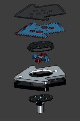
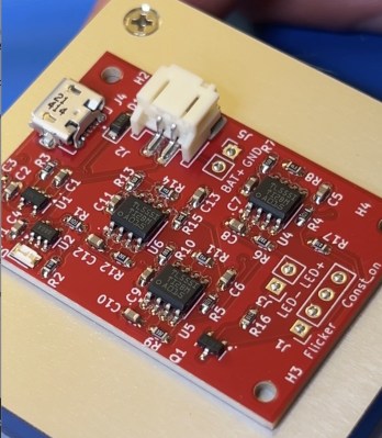
While the “should have used a 555” meme is strong around these parts, we absolutely agree with [Kelvin Brammer]’s decision to make this 555-shaped plug-in replacement for the 555 timer chip using discrete parts, rather than just a boring old chip.

As [Kelvin] relates, this project started a while back as an attempt to both learn EDA and teach students about the inner workings of the venerable timer chip. The result was a 555-equivalent circuit on a through-hole PCB, with the components nicely laid out into the IC’s functional blocks. As a bonus, the PCB was attached to an 8-pin header which could be plugged right in as a direct replacement for the chip.

Fast forward a few years, and [Kelvin] needed to learn yet another EDA package; what better way than to repeat the 555 project? It was also a good time to step into SMD design, as well as add a little zazzle. While the updated circuit isn’t as illustrative of the internal arrangement of the 555, the visual celebration of the “triple nickel” is more than worth it. And, just like the earlier version, this one has a header so you can just plug and chug — with style.

Want to know how the 555 came to be? We’ve covered that. You can also look at some basic 555 circuits to put your 555-shaped 555 to work. We’ve even seen a vacuum tube 555 if that’s more your thing.

Back To Basics With A 555 Deep Dive

Many of us could sit down at the bench and whip up a 555 circuit from memory. It’s really not that hard, which is a bit strange considering how flexible the ubiquitous chip is, and how many ways it can be wired up. But when was the last time you sat down and really thought about what goes on inside that little fleck of silicon?

If it’s been a while, then [DiodeGoneWild]’s back-to-basics exploration of the 555 is worth a look. At first glance, this is just a quick blinkenlights build, which is completely the point of the exercise. By focusing on the simplest 555 circuits, [Diode] can show just what each pin on the chip does, using an outsized schematic that reflects exactly what’s going on with the breadboarded circuit. Most of the demos use the timer chip in free-running mode, but circuits using bistable and monostable modes sneak in at the end too.

Yes, this is basic stuff, but there’s a lot of value in looking at things like this with a fresh set of eyes. We’re impressed by [DiodeGoneWild]’s presentation; while most 555 tutorials focus on component selection and which pins to connect to what, this one takes the time to tell you why each component makes sense, and how the values affect the final result.

Curious about how the 555 came about? We’ve got the inside scoop on that.

Continue reading “Back To Basics With A 555 Deep Dive”

A 555 Can Even Make Your Car Indicator More Visible

Modern cars often come with white marker lights or daytime running lights that are on all the time, as a supplement to the primary headlights. The problem is that in some vehicle designs, these additional lights tend to make it harder to see the indicators when they’re on. [nibbler] had this very problem, and decided to solve it with a special interrupter circuit that cuts the daytime running light when the indicator is on. Even better, they used a 555 to do it!

The circuit is a simple monostable 555 circuit with an active low output. It’s triggered by the indicator signal. When the indicator is on, the circuit drives a relay to switch off the power to the daytime running light. Two copies of the circuit were built, one for the left side, and one for the right side of the car. This means that when the orange indicator is lit, it’s not being overwhelmed by the white daytime running light next to it. In fact, many automakers now program this behavior into their lighting by default.

It’s a nifty hack with a real positive safety impact. We’ve featured some other neat indicator hacks of late, like these tidy sequential indicators. Meanwhile, if you’re hacking on your own automotive lighting solutions, don’t hesitate to let us know!

Weird 555 Function Generator Uses Feedback

There are plenty of designs out there for sawtooth and triangle function generators, many of them using the humble 555 IC. Few are readily voltage controlled, making them difficult to work with using a DAC, though. Enter this useful design posted to EDN!

The nifty design allows both waveshape and amplitude to be controlled via voltage. You could hook up a couple of  potentiometers and call it done. Or, even better, you can control these parameters via PWM output from a microcontroller. Handy, no? It’s achieved by a fancy routing that sends feedback from the 555’s output pin to the CV input, instead of the usual design that uses the THR and TRG pins instead. The design also allows the production of both symmetrical and asymmetrical triangle waveforms, and as a bonus, the whole oscillator draws less than 4 mW of power.

If you’re looking for a nifty triangle/sawtooth generator that sits neatly in your otherwise-digital design, this could be for you. Or, you might like to explore the sheer mountain of other 555 hacks we’ve featured over the years. We even held a contest! If you’ve got new 555 hacks the world needs to see, don’t hesitate to drop them into the tipsline.


Fixing A Reflow Oven’s Conveyer Belt With An NE555 And Stepper Motors

Some design choices on manufacturing equipment really leave you scratching your head for a while, as recently happened to [Chris Cecil] when the belt on a reflow oven’s conveyer snapped. Although the solution seems simple enough, getting a new belt on the thing would involve essentially taking the entire machine apart, before reassembling it again. Thus the frayed belt went through the oven over and over until during a recent production run of Smoothieboard controller boards until [Chris] heard a funny noise and the conveyer ground to a halt.

Moving the conveyer by hand kind of worked, but with a more permanent fix urgently needed to finish the production run, two stepper motors took the place of the belt, which just left driving these steppers to keep the conveyer moving in sync. Lacking a simple Arduino board to toss at it, and with a Smoothieboard being absolute overkill, [Chris] figured that a humble NE555 timer IC ought to do the job just as well.

Using a project on Hackaday.io by [KushagraK7] as the starting point, and a 1992-vintage NE555 IC harvested from an old project, [Chris] managed to put together a basic stepper driver that uses the NE555 to provide the timing signal. In addition to restoring basic functionality like starting and stopping the conveyer belt, [Chris] added a new feature with the reversing of the conveyer direction. Along with some cobbled together components to physically rotate the conveyer’s two rollers, it restored the reflow oven to working condition.

And one day the prototyped driver board will be updated to a proper PCB. It’s only temporary, after all :)

Continue reading “Fixing A Reflow Oven’s Conveyer Belt With An NE555 And Stepper Motors”