If you want to measure voltage you reach for a voltmeter. Current? An ammeter. Resistance? An ohmmeter. But what about measuring AC power? A watt meter? Usually. But if you know what to do, you could also reach for your oscilloscope. If you don’t know what to do, [Jim Pytel] has the video answers for you. Truth is, an oscilloscope can measure almost anything if you know how. [Jim] shows how to measure the voltage and current in a circuit and then it is simply a matter of doing a little math, something modern scopes can do very easily.
We like that [Jim] shows a circuit and how the math works before he verifies the math with the scope. Of course, theory doesn’t always match practice. The method uses a small current-sensing resistor that throws readings off a bit. The scope and signal generator are not perfect, either. However, the results match up pretty nicely with the computed results.
Electronics can be pretty abstract and the oscilloscope is probably the best tool for visualizing what’s going on inside. It used to be that hobbyists had to buy old surplus scopes to get something nice, but now you can get a fantastically capable scope for a few hundred dollars brand new.
Of course, if you like, you can pay over a million. Or, perhaps you’d like to visualize your signals in flames.


Just be aware that precision on these readings sometimes (depends on the manufacturer) varies with the display settings. So make those traces as large as you can (without cutting any of the waveform off) to get the best results.
Still, my experience has been that you do need to double-check the results, since they can be off by 10% or so.
“Of course, theory doesn’t always match practice. ”
“Theory and practice are the same, in theory.
Theory and practice are not the same, in practice.”
-unknown
I’m still off in this tangent of antenna and probe theory and application study. When I realized what can be measured with an oscilloscope in either the time or frequency domain… I was like… drooling and wanting to be able to make all my probes (including antennas, attenuators, filters, amps, etc).
Seems like the oscilloscope (and not damaging it) is what really lured me into learning more electronics and RF engineering.
I guess the spectrophotometers and other spectroscopes didn’t really have that inquisitive like effect. That was more like… what are those peaks… wow… at a higher resolution the spectra looks different and there’s new peaks!!! How do I Homer Simpson this so people don’t make mistakes in the lab throughout the lifecycle???
i need a more noob-level guide to scopes. i still get surprised when hooking my ground probe to anything other than real ground results in a short circuit
Greg A,
I got you covered bro. Here’s a whole playlist about oscilloscopes from the bottom up:
https://www.youtube.com/watch?v=i7VDr07n0Y8&list=PLdnqjKaksr8ocgczyYdSeNpVVvWQ8Ns4v
I’m the author of the above lecture and this particular lecture is intended to be for “intermediate” users. The attached playlist includes a bunch of other preparatory material. Enjoy!
As part of another project, I used my ‘scope to measure power and power factor a few years ago. The article on how it was done is located at:
http://www.buchanan1.net/bulb_tests.html
Also, the results were compared to a “Kill A Watt” power meter.
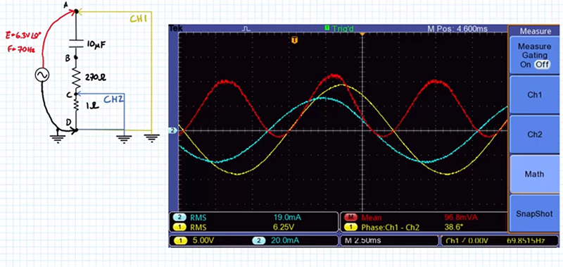
The simple multiply routine in the scope does not take the voltage drop across the 1Ω resistor into account. In reality he should be taking (CH1-CH2) X CH2. As a practical matter though the error is less than 0.5% (1/270) so it’s not much of an error source.
Something to keep in mind though if your sense resistor is an appreciable fraction of total impedance being measured.