[Ivan Miranda] is always experimenting with 3D printing, and recently has been taking his work on the water. His latest creation is a racing paddle boat, but its performance left [Ivan] with a need for speed. Cue the development of the 3D printed water jet engine (YouTube link, embedded below).
The basic principle of operation is simple. Water is sucked through an inlet, where it is accelerated by a turbine driven by a brushless motor. This turbine, in combination with stator fins, forces the water through the outlet, propelling the boat forwards in the process.
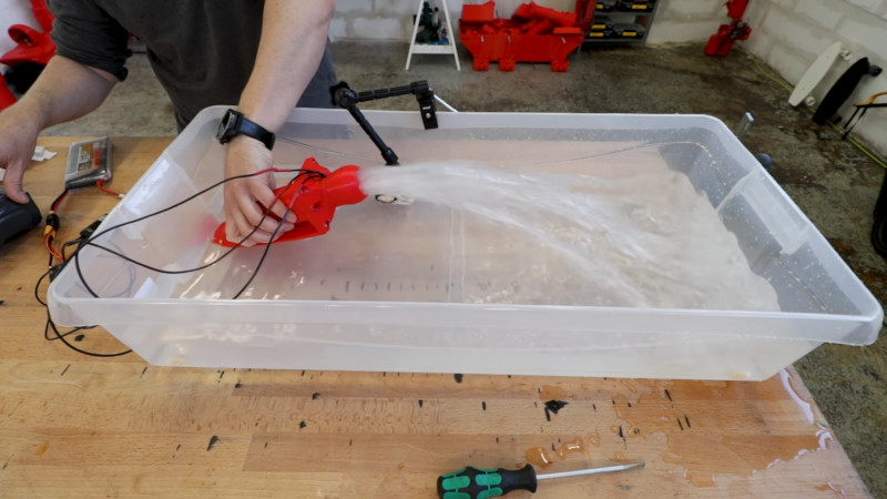
The first prototype is printed in PLA. Tolerances are good, thanks largely to [Ivan]’s experience and well-calibrated printers. After assembly, the engine is fired up, to great results. After sourcing a series of larger tubs in which to test the device, the engine is finally run up to full throttle and appears more than capable of shifting a serious amount of water.
We’d love to see a proper instrumented thrust test, particularly one that compares the device to other water jet drives on the market. Brushless motors make a great drive solution for RC boats, so we’re sure [Ivan] will be tearing up the lake real soon. Video after the break.
https://www.youtube.com/watch?v=CP3alznCPwg&feature=youtu.be


Neat, wonder if it will scale up a tad to slap one on the bottom of yer canoe.
Thats the plan.
Watch every friday night 9pm GMT!
An issue with his design is putting the motor in the water. If he made it like a normal jet drive with the motor ahead of it, it could move a lot more water. He’d have to figure out a shaft seal.
I don’t think so actually. There are commercial versions of this which also put the BLDC motor directly in the water.
Let’s dive into this. :)
Most BLDC motors terminate the magnet wire for the coils directly in the plugs, so that’s the only place the electrical system would be exposed. Seal those up with a touch of RTV.
The bearings being underwater will run them out of lubricant eventually and could corrode. Clean them and lube them with a heavy weight grease, or just replace them with sealed or ceramic bearings.
The rotor will create some drag by needing to spin water around inside it, but this will also cool the motor tremendously well. You could easily double the power applied if you have the magnetic flux density to use this. You probably do.
+1 Daren. I heard the guy from openROV on the embedded.fm podcast recently say this discovery was a breakthrough for their projects, allowing them to drive BLDCs at much higher voltages and resultant current. If anything, Ivan should be aiming to enhance the flow of water through/past the motor.
Ps, I was really interested after watching Ivan’s video and found plentiful supplies of RC model moulded jets on Aliexpress. Lager common size was a 40mm outlet diameter and they have a left-right vane/scoop for servo direction control. They move the drive shaft through the outer casing so you can keep your motor dry, if you really want to.
Yeah, the ones with the shaft are the usual design, also very commonly used on freewheeling gas turbines.
But with such a construction you’ll need to take great care about sealing the hole where the shaft goes into the casing. It would most certainly require some lubrication for the shaft seal. Plus you’ll need to figure out how to cool the motor.
Both these problems can be easily solved on a system running with water by putting the BLDC into the stream.
Prop shaft packing glands for model boats have been available for a very long time, so that’s not any problem at all. With the motor in the water duct, the duct has to be much larger to move the same amount of water.
I also think he could get away with not having to keep the entire assembly under water (it would flood during operation, but could streamline the system and make directional thrust easier). All he really needs is a scoop that is sufficiently submerged that water closes off part of the inlet. If the heigh differential/distance between that position and the top of the path is sufficiently small, it would easily create enough of a vacuum in the remaining limited air space for external pressure to drive water up into the system.
The HaD article about the late Rex Garrod recently pointed out that he ran electric motors underwater at about 4x over-voltage due to the added cooling (on a giant animatronic shark, naturally).
The bearings may wear out and any exposed contacts will corrode but there’s ways around that.
Damnit that was supposed to be a reply to smerrett79, has HaD borken the comments thing or what?
Ok what gives on the comments, testing testing…
I would never imagine these motors can work while submerged inside water :o
(Btw, nice project!)
They’re brushless and the electricity never comes in contact with the water, assuming any circuit board in the motor is coated with something to seal it. Where these are 3 phase motors there may not be any electronics in them, unlike 12 volt brushless motors used in computer fans.
The main issue is the bearings. On most of these brushless outrunner (the outside spins like a Gnome rotary) the bearings are not designed to be run submerged in water, or any other liquid. They *can* be run submerged but the lubrication must be periodically re-done.
this is awesome. couple of questions:
– any way to leave a description or link of the gear you’re using? motor, esc, batteries. did you say 920kv brushless?
– would that work in seawater (salt adding issues to the motor being submerged)?
thanks!
What is the morot you are using here?
Thank you for stating that the water is forced into the output of the waterjet by the turbine working in concert with the stator fins to move the boat forward. My sister said that the damage to her water jet turbine prevented the boat from moving. I’ll track down Omax waterjet replacement parts for my sister to replace her turbine.