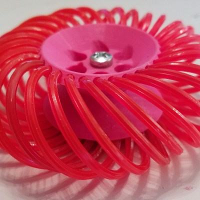
What do you do if you want a robot with great mobility? Walking is hard, and wheels are good enough, especially if you use the ‘wheels within wheels’ Mecanum setup. But you need torque, too. That’s what makes this entry into the Hackaday Prize so fantastic. It’s a Mecanum wheel of sorts, with an integrated gear set that produces a phenomenal amount of torque using a small, cheap stepper motor.
 The wheel itself if 3D printed and fully parametric, using nylon weed wacker filament for the treads. This allows the wheel to scoot back and forth like a Mecanum wheel, or at the very least like one of those hyper mobile wheeled robots you see from time to time. It goes backwards, forwards, and side to side, and also has a zero turn radius.
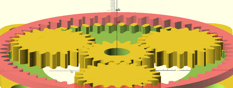
A 3D printed Mecanum wheel is great, but how on earth do you drive it? That problem is solved with this hybrid planetary/strain-wave 3D-printed gear set. [Daren] has created a very compact ‘single’ stage gear set that fits right on top of a stepper motor. It’s thin, flat, and has a gear reduction of about 66:1. That’s a lot of torque in a very small package. Both of these projects are combined, and together they represent a freaky wheel with a lot of torque.
Even though [Daren] doesn’t have a robot in mind for this build, these are most certainly the building blocks of a fantastic robot, and a great entry in the Hackaday Prize.


The stepper was just used for the initial test as the OpenSCAD source I borrowed from a previous project used one. The target application is actually a BLDC motor or a regular DC motor. I have a box full of the latter, so those are being modeled going forward.
That’s pretty slick!
Is it healthy for a stepper to be moved from the spindle? I’m hoping your comment above means you don’t mind if that’s damaged.
I’d love to see what the failure mode is, assuming the motor is strong enough to break the plastic. I’m predicting it will be the twisting motion on the planet gears’ cogs where they mesh with the two outer races. Since those are half the normal gear height, they’ll likely crack first. Increasing the number of planets would help; you may be able to fit 5 in there without too much rework.
You could make the reduction ratio ridiculously high by making it two staged. Picture putting teeth on the outside of the top piece that rotates.. now picture shrinking that down and using it as the inner gear that turns the planets on a second stage. You could use a tiny, low-torque motor and still end up with lots of torque!
What is in that video is the very first version I ever made.
The current version uses a larger sun, split planets for lower backlash, and works with 3 or 6 planets.
It’s (almost) parametric though so you could just change a couple variables and render what you want. Planet count, gear teeth/ratios, gear height, diameter, pitch angle, etc… are all just variables. I’m still missing a proper definition for one variable relationship though, so you still have to tweak that one.
This is interesting for building a low cost astronomy tracker (barn door tracker). I currently use a stepper with a planetary gearbox, but they are somewhat expensive. I’d like to show others how to do this more inexpensively.
The initial prototype did have some backlash and so would be inappropriate for your application.
However my co-developer on this project intended to use it for a SCARA arm and so we did come up with an easy way to eliminate the backlash, but with a lower maximum torque output. Split one of the planets and spring load it, and no backlash. Watch the project and when that is ready, we will post it.
Backlash is not a problem. These things go around once a day. Every 12 hours the load will shift as the center of mass passes the meridian. Exposures are typically only minutes long.
Feel free to message me on Hackaday.io and I’ll see if I can make it easier for you to implement.
The OpenSCAD source for generating the transmission is now fully parametric (driven by variables you can set) so the rest is basically just ‘what else do you need where’.
This is beautiful!
If you don’t want to change direction of rotation, I would expect you can put the finer pitch on the output ring by adding instead of subtracting num_planets:
output_teeth=ring_teeth+num_planets;
Have you played with that at all?
You are correct, and the current version does just that.
For the original the teeth meshed better when the output ring gear had less teeth than the input ring gear as I was fudging the output ring gear tooth pitch to make it work.
The latest version splits the planets into two layers and as such each layer can use the matching gear pitch for the ring it is meshing to, and so I was able to un-reverse the rotation then without consequence.
“adding instead of subtracting num_planets:”
Yes, I want Pluto back!
Funny thing, there is a rover project named Pluto as well.. :)
Typo: “The wheel itself if 3D printed”, if->is
That aside, I really need to try weed whacker filament
Wow, I really like the improvements in 1.0. This is excellent work.
Thank you. The ability to render a full transmission/wheel just by just setting a few variables was always the goal(s) here.
An article posting about a project (or two) tends to accelerate the pursuit of those goals though. :)
In the eight or nine times I’ve been *here*, I’ve had a grand total of *one* of those projects ready for public consumption.
MPRT-1.01.scad is now posted and is basically ready for use with all the short term goals fulfilled. filamecaun.3.2.scad is out as well and all the dimensions work, but the concept itself is still un-tested.
If you like this, you should really visit GDFW:
https://www.youtube.com/channel/UCERyl8JwFJuCISJfcnpCvwA
Nice looking site, and I like the concept! I have yet to dive into any of the actual design documents though. Thank you.
This is excellent work. Thanks for sharing it.
This is very similar to how the input reaction carrier and planetary in a car’s transmission is designed. The way I’ve seen it done in the transmissions I’ve worked on. The input shaft meshes into the center of a hollow sun gear. The sun gear meshes into the center of the planetary gears. The reaction carrier meshes around the outside of the planetary gears. Almost always there is a thrust barring between the reaction carrier and plantary carrier. It’s a pretty important barring to have. I have an input shaft in the garage which looks like someone got artsy with a blowtorch, what happened to it was that barring failed and overheated the shaft. Sitting one on a desk and spinning it, a good barring it’ll spin for a few minutes but a bad barring stops about as fast as a bike tire with rubber brakes pressing against it. It’s remarkable just how big of a difference cutting out the friction in that one spot makes.
I love this design.
If you can, can you produce a tutorial on how to use your Openscad software? I would love to try 3D printing one of these for use in trying to replicate the motor packages used in the MIT robotic cheetah. https://hackaday.com/2019/05/29/robotic-cheetah-teaches-a-motors-class/