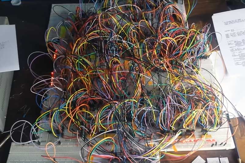
Did you ever start a project that you felt gained a life of its own? This project by [Paulo Constantino] is an entire CPU named dreamcatcher on breadboards, and is a beautiful jungle of digital. On top of that, it works to connect to an analog VGA display. How cool is that!
Designing an ALU and then a CPU is a typical exercise for students of digital design and is done using VerilogHDL or VHDL. It involves creating an ALU that can add, subtract etc while a control unit manages data moves and the like. There is also a memory fetch and instruction decode made up of de-mulitiplexers and a bunch of flip-flops that make up registers and flags. They are as complex as they sound if not more.
[Paulo Constantino] went ahead and designed the whole thing in Eagle as a schematic using 74HC logic chips. To build it though instead of a PCB he used breadboards. Everything from bus decoders to controlling an external VGA display is done using jumper wires. We did cover a video on the project a while back, but this update adds a video card interface to the build.
The CPU updates the display buffer on the VGA card, and in the video below shows the slow and steady update. The fact that the jungle of wires can drive a display is awesome. He has since started working on a 16-bit version of the processor and we’d love to see someone take it up a notch.
For those more accustomed to the PCB, the Z80 membership card project is a great build for 8-bit computer fans.
Thanks to [analog engineer] for the tip.


Strange.. This was here before, in the shape of the Big Mess of Wires project.
They mention that. This is a post to indicate the project was updated to include VGA.
The BMOW (Big Mess Of Wires) project is different (different author , designer , project) and has it’s own website –
https://www.bigmessowires.com/
Granted: a lot of breadboard projects look like a big mess of wires (in lower case).
A most excellent project!
My kinda mess!
Wow, it uses a 120 bit wide microcode format, with 16K words.
Yes! 1,329,227,995,784,915,872,903,807,060,280,344,576
different data transaction methods, not all of them useful of course.
So is it a CISC LOL!!
Kind of design your own instruction , Picasso style!
Yes a hack!
OMFG.
No-one say the word “debug”
ah, have to be wired to be able to debug
Interesting that you opening statement mentions God and your closing statement is likely to involve praying.
Either I have been cloned or a time worm just closed ends.
Wow this more surreal than I thought. My heart stopped during surgery after multiple organ failure in early 2021 and I was technically dead while transferring to Intensive Care Unit. The top pot is from 2019 before then and could well have been the previous me.
I have just answered the previous life me.
Work on your layout! This is not even an elegant disaster.
I appreciate a fine rats nest like this but maybe some ribbon cables or harness wrapping might help it look less like the intention is to make it a mess. Lots of open space on boards also. Not feeling it was ‘thought out’ at all. Functional so everything else griping and it is cool.
I think they are all crazy though. Look at the drugs they pump into themselves
This looks like shit. Stop trying to look like the ‘mad genius’. Messy doesn’t mean complex, it just means messy.
Some of us prefer to dedicate our time to getting something working than making something pretty
You’ll often find some upfront prettifying time will save you orders of magnitude more make-it-work time later in the project.
Link us up to some of your tidy projects, please.
That’s great idea for assembly standards of spy drones. You don’t have to worry if it falls into enemy hands. Driving foreign scientists into complete madness could be set as secondary objective.
I couldn’t stand that– what if a single wire became unplugged (as easily as it can from a breadboard). Hours and years to debug. To make this work is madness.
Plus, those jumper wires are probably ebay/Chinese specials, which ime means they’ll be shoddy quality and break internally (normally at the pin/wire interface) just for the hell of it at random.
I’ve seen software that’s better structured than this! Not very often, granted :)
This is awesome and anyone who disagree are wrong. Welcome to the Internet.
Day 1 for the PFY
Working for the BOFH
Rewiring all the network cabs
anyone else be bothered googling them their acronyms and care to post what they done did find?
PFY – Pimply Faced Youth, a.k.a. The Geek or The New Guy – the intern and understudy to the
BOFH – Bastard Operator From Hell, a.k.a. The Sysadmin, The Bastard, That Mothf$%#er, or My Lord, as I like to be referred to.
i have a number of problem with breadboarding large projects like this. they are called cats.
Catastrophe
The problem I have with breadboarding large projects like this is procrastination. To me this is just amazing.
I know the exercise is to build a CPU and ALU, but what architecture does this particular project follow, if any?
Eagle was the wrong tool.
Hah, I know I’m going to get some nasty responses here but… considering that this ended up built on breadboards… Should have used Fritzing!
Yah, Yah, I know, Fritzing. But hey, maybe there wouldn’t be quite as much of a wire mess that way. Components could be re-arranged on the virtual breadboard to minimize mess, connections could be checked and then it could be used as a guide to populate the real breadboard.
I wish KiCAD would develop a feature like that. I wonder if they would accept code contributed toward that end. I am imagining two new tools added to KiCAD. One is a breadboard editor that allows one to create a model of their breadboard. The other consumes both that model and the netlist and allows one to layout the components, jumpers, etc and validates that all the connections are correct. I would use that AND create the PCB too at the end when breadboard-design phase is done with.
Holy mother of rats nest! Imagine the signal integrity on that!! I’m surprised it works!
Ah sweet memories of the late 60’s when a full semester of EE class was spent going over each line and chip in a Data General Nova Mini Computer to learn computer cpu design!!!
The amazing thing is that it runs Quake at 87fps
New ways new ways I dream of wires aka robert palmer gary numan