The ’80’s and early ’90’s saw a huge proliferation of “personal” computers, spawning an army of hacker kids who would go on to hone their computing chops on 8-bit and 16-bit computers from brands such as Sinclair, Commodore, Acorn, Apple, Atari, Tandy/RadioShack and Texas Instruments. Fast forward to 2017, and Raspberry-Pi, BeagleBone and micro:bit computers reign supreme. But the old 8-bit and 16-bit computer systems can still teach us a lot.
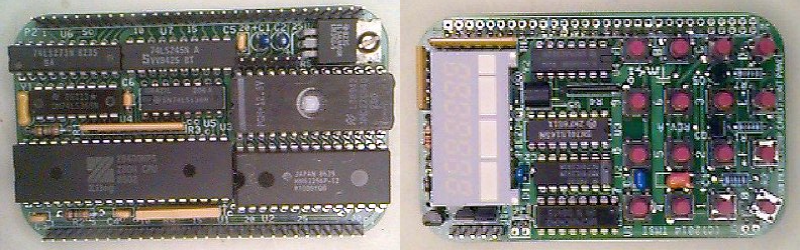
[Lee Hart] has built the amazing Z80 Membership Card — a Z80 computer that fits in an Altoids tin. His design uses generic through hole parts mounted on a PCB with large pads, thick tracks and lots of track clearances, making assembly easy. Add to this his detailed documentation, where he weaves some amazing story telling, and it makes for a really enjoyable, nostalgic build. It makes you want to get under the hood and learn about computers all over again. The Z80 Membership Card features a Zilog Z80 microprocessor running at 4 MHz with 32k RAM and 32K EPROM, loaded with BASIC interpreter and monitor programs. A pair of 30-pin headers provide connections to power, I/O pins, data, address and control signals.
To accompany this board, he’s built a couple of companion “shield” boards. The Front Panel Card has a 16-key hex pad, 7-digit 7-segment LED display and Serial port. [Lee] has packed in a ton of features on the custom monitor ROM for the front panel card making it a versatile, two board, 8-bit system. Recently, he finished testing a third board in this series — a Serial/SD-Card/RAM shield which adds bank-switchable RAM and SD-card interface to provide “disk” storage. He’s managed to run a full CP/M-80 operating system on it using 64k of RAM. The two-board stack fits nicely in a regular Altoids tin. A fellow hacker who built the three-board sandwich found it too tall for the Altoids tin, and shared the design for a 3D printable enclosure.
[Lee] provides detailed documentation about the project on his blog with schematics, assembly instructions and code. He’s happy to answer questions from anyone who wants help building this computer. Do check out all of his other projects, a couple of which we’ve covered in the past. Check out Lee Hart’s Membership Card — a similar Altoids tin sized tribute to the 1802 CMOS chip and how he’s Anthropomorphizing Microprocessors.
Finally, we have to stress this once again — check out his Assembly Manuals [PDF, exhibit #1] — they are amazingly entertaining.
Thanks to [Matthew Kelley] who grabbed one of [Lee]’s kits and then tipped us off.


How about a color video board which also has inputs for a mouse and keyboard?
You can keep your color and fancy mouse; I’ll stick to my Wyse 100 serial terminal just as God intended.
Hush, you’ll hurt my adm3a’s feelings.
Yeah, The graphics capabilities were really a defining feature of 1980’s home computers and arcade machines.
All the same this membership card is beautiful in it’s own right with those retro aesthetics – especially the windowed UV EPROM with those visible die bond wires.
It would be the delight of CP/M fans that are used to a console interface.
As a minimum system it does very well.
Now days the Video is the harder part of a retro-computer. Simple 16 color QVGA can be done with a simple CPLD but not everyone does VHDL or Verilog.
There are other alternatives like GameDuino and I have seen some on hackaday.io as well.
https://hackaday.io/project/6309-vga-graphics-over-spi-and-serial-vgatonic
PS2 keyboard and mouse can work fine with a retro CPU but it can be a CPU resource drain to keep polling with such a simple interrupt scheme. An alternative would to be to used a common AVR for the interface and the same AVR could probably generate simple video.
A reasonably fast AVR can bitbang 240×240 VGA with some extra SRAM.
http://quinndunki.com/blondihacks/?p=1040
To keep with the spirit of this design you’d probably want to use a 6845 CRTC for video signal generation. As an address generator you would also need some logic to read the memory at the addresses and turn it into an output, either text based or with a CPLD a graphical output (c.f., Amstrad CPC).
IMO it might be easier to source a decent serial character mapped display and ignore all the video stuff. Or use an IIC/SPI video chip, but that’s not really in the spirit of the 80s either. And you’d need to create the IIC/SPI interface too.
Yep, that was the difference between computers back then.
The Amstrad CPC was actually the odd one out as it used a purely bit-mapped display like modern computers. This was very slow as the low MIPs CPU wasn’t good at changing a large number of pixels. One CPU write could only change 2, 4 or 8 pixels. You had to do 32, 16 or 8 read-write cycles to change one character. The CPC did however have easy scrolling in any of 8 directions so it was very good for scrolling games. The CPC used DRAM memory chips.
Most of the other platforms used character based displays and took advantage of the small SRAM memory chips available at the time. Because the SRAM chips were small you had access to separate fragmented data and address buses so the SRAM could have a linear mapping on the CPU address bus and a more complex mapping on the output side.
An example –
2kB SRAM character map of say 50 x 40 screen characters with each byte representing one character
The data from the above SRAM then indexes 3 separate 2kB SRAMs for Red Green and Blue so that the character data bus goes to the higher address pins of the RGB SRAM and the 6845 controls the lower address pins of the RGB SRAM.
In this way one CPU write will change 64 pixels including changing pixel color.
This is hard to achieve now as SRAM chips are huge by comparison so it’s hard to justify having 4 SRAM chips. It can be done with FPGA that has blocks of BRAM for example the Gameduino, but HDL is not everyone’s cup of tea. CPLDs just don’t have enough pins to drive 4 banks of SRAM. I’d love to remake the Gamduino with a parallel interface for a retro CPU but the HDL is Verilog and I only know VHDL.
This is a good example of an authentic retro video system that even has some quite advanced features –
https://hackaday.io/project/20781-breadboard-color-computer-from-ttl
What I would like to make one day is a DIP style board that has the same pinout as a 8kB SRAM and has a VGA connector on it so that those who want to do the retro computer can plug it in inplace of a real SRAM chip.
I also have some samples here of SRAM chips that have a builtin DMA output but you would need three ships for 8 colors (they’re cheap anyway) and I don’t quite think that they are fast enough for VGA but should be fine for NTSC or PAL.
I might add a note about old Arcade Machines.
They used some very complex methods to get such appealing displays.
Quite often there were two circuit board of about 14 inches by about 20 inches with one piggybacked on the other.
The piggybacked board was the video card and the other board was every-thing-else.
They had megs of ROM for backgrounds for scroller games to take the load off the CPU. EPROM was cheaper than SRAM back then.
With all of the complex image for scrolling don’t in hardware, the CPU only had to work on the action character(s) which was a small load by comparison.
vector graphics, like asteroids, battlezone, and tempest. and what’s a mouse? did you mean ‘lightpen’??
Now hold on, I distinctly remember using an optical mouse on Sun 3 workstations in the 1980’s…
an embarrassment of riches; you also had megs of ram and networking, too, I think!
Modern vector graphics to VGA is quite an interesting idea and very doable with modern chips. It wouldn’t quite have the perfect linearity of the originals but with modern LCD resolutions you would need to have your eye close to the screen to see the quantization.
huh hadn’t thought of that, but wouldn’t that be tantamount to doing raster? but unless you want to play with the bulk of CRT, then that would be the way to go!
Technically it’s still raster and it certainly wouldn’t satisfy the purists but rewinding a vertical deflection yoke of a CRT involves high voltages, dangers and many of the skills required are lost now, especially convergence re-adjustment.
On the other hand a simple low voltage digital circuit that drives a VGA monitor is easy to make with modern skills and would allow people to safely play with a pseudo-vector display.
The problem for me is that I don’t know what the communications protocol was. I think the old CRT vector displays had a separate CPU to drive the vector output and as such they would have had proprietary protocol.
Perhaps just a bunch of registers with start and end co-ordinates along with some color information would do. It could be SPI and perhaps a Arduino shield version.
FPGA would be overkill and CPLD might still be more expensive than a CPU based solution. For a Micro-controller version it would need a very simple and fast CPU. Any suggestions?
hmm. You know RÖB I’m not sure there was a protocol per se, but rather just analog ramps for the X and Y deflection and then turning the beam on/off (and I guess thee beams for things like tempest).
I /believe/ there are plenty of ‘oscilloscope display’ projects out there (look for clocks — everyone makes clocks), and they are principally vector displays using the o-scope in X-Y mode. So it’s been done with microcontrollers.
But now you have me thinking about it more seriously. One advantage of vector over raster at the time is that you didn’t need a hunk of expensive memory for a frame buffer, rather you used then-comparatively-cheap analog circuits to generate ramps (well, hyperbolas) of varying amplitude and period. Now ram is cheap, and external funky analog circuits are expensive. So definitely not modern-day practical!
But we do have D/A converters on many/most uC, so you could emulate the analog sweep circuits with that. What would it take? Well, I recently (ok 2 y.a.) used a PIC32MX at 80 MHZ to generate RGB VGA over SPI (using a modified Paul Di Lascia technique). That was raster, which, when you think about it, what is a raster display but vector display of an ocean of horizontal lines, intensity modulated, right? So almost surely any practical display output will be far fewer lines than as many as it takes to raster scan the entire display surface. (Now that I write this, I think that was probably another practical advantage back in the day whose economies did not scale).
The project I mentioned worked really because I could use DMA to squirt out the three channels and leave the CPU to do it’s business separately. But in this case I’m not sure you need it, and even interrupt-driven transfer should be adequate and real-time. Since this is vector, the cpu needs scale with the complexity of the image displayed, so you can adjust to what you can handle. I would wager you would even be able to get the ever-popular Blue Pill to do it while sitting around laughing with friends sipping champagne on a balmy April day, and still unnoticeably keeping up with servicing real-time display chores. But that chip has so little RAM and ROM, that you won’t be able to fit in an emulator for the main CPU, alas. [NOTICE TO BELOVED CHINESE VENDORS OF AMAZING THINGS: PLEASE MAKE A BLUE PILL WITH AN STM32F415. I WILL PAY TRIPLE.].
Anyway, getting back to your original point, I’m not sure that making a raster emulation of vector output to be put on a fundamentally raster output device is especially useful, because such an emulation would be intrinsically raster to start, converting to vector, only to convert back to raster, so why not just go straight to that? But I think there is some merit to your suggestion if you don’t have control over both sides, so a raster emulation of vector input (I think you suggestion) is useful if you want to replace a vector display — maybe an arcade game, who knows. And a vector driver output is useful if you want to drive an existing display (maybe a laser X-Y system? who knows?).
At any rate, in the end, vector is very pretty, retro, and somehow brings back scents just thinking about it. It probably appeals to a similar sensibility that cleaves unto nixies and numitrons. Hmmm, cozy…. !Do not touch while in operation!
There’s still old arcade collectors / restorers who have the skills, knowledge, and tools, either salvaged or home-made, to work with vector monitors, even *colour* vector monitors. The hardware for each starts from a bare vector monitor, with magnetic deflection. In fact the monitor is counted as part of the whole thing, there’s no logical separation between monitor / controls / PCB / CPU or even software, a machine is a single whole piece, and a collector needs to know how to do everything.
Between, say, Lunar Lander and Asteroids, different methods were used to drive the vector CRT. Some used digital counters to generate the in-between lines between vector points. Some used analogue integrators. The technology changed as Atari’s engineers went from one brainwave to another. The information, particularly old technical-subject interviewss and documents, with the old geniuses, is still out there. Arcade collectors are doing what they can to archive it against being lost.
greenaum’s points are well made, and history is being incrementally lost save for the effort of retro folks who are ersatz archivists.
@[ziggurat29]
Agreed, CRT’s are all but extinct. They’re not being made anymore and even worse supplies HV Flyback transformers (LOPT’s) are drying up to. A tube will outlast several HT transformers and a couple of deflection yokes.
I have an old 27″ CRT TV that I will probably through out as it’s a lot of work to convert it for vector graphics and I simply don’t have that much interest when I can make a digital circuit to play with vector graphics on a LCD monitors.
I looked at the Cyclone II series and they have more BRAM than needed and less macros that would be comfortable but still doable. Parallel processing is the better way for this.
this is great though I still await a credit card size phone/calculator thin C64 orTRS-80 gadget with fold out membrane KB and maybe OLED screen. For modern compatibility I would even go for something like that with ARM, ESP, even Atmel under the hood.
Why not? But it’s the human interface devices that are the most expensive part. And these days, that’s the only thing that needs to even be a visible part (well, except for battery; we still have a lot of constraints there).
I was looking at an arcade board I’ve got lying around and it has a z80 on board and was thinking maybe I should build a computer out of it.
That guy has some other interesting projects on his web site as well.
which game? dump the rom, please (if it’s not already available)
It is a computer. Just add a decent keyboard. Not surprisingly, it would be excellent for programming games.
The Multi-Arcade-Machine Emulator scene is a great resource. You will find schematics and probably port maps and a commented disassembly.
All but the oldest and new machines used a wiring harness pinout called JAMMA.
There is a wealth of literature out there on how to port Z80 CPM to other hardware and it’s far easier than you probably expect. Then you can add one of the very many BASIC languages.
The output will be RGBVH and you can use a converter to go to most standards like PAL, NTSC, VGA etc.
Nice job.
Keep up the good work.
They are ‘daughter’ boards. Stop trying to reinvent stuff that already exists. :)
I used to have an old toy vtech “pre-computer power pad” that ran a z80 and had a basic compiler built in along with the cheezy education apps. It’s a shame I gave it away.
This guy describes it.
http://chadillac.github.io/2011/01/04/vtech-pre-computer-power-pad-i-love-thee/
As long as it fits into an altoids tin. Urg.
Lee’s boards can also let you use the older processor architecture with modern peripherals – I have had a web server and telnet-based games on mine with an Ethernet module
https://olduino.wordpress.com/about-2/about-olduinoz/
It’s definitely a fun project to build. You can build just the bottom CPU board and communicate with it through TTL Serial. The Monitor includes Micro BASIC by Dave Dunfield. Then, you can add the top board for a nice LED/Keypad monitor operation that was built to resemble the Heathkit H8 computer’s PAM monitor (monitor lives in the ISR). The serial port of course is bit banged, but features a full duplex bit bang routine. The monitor is capable of Xmodem, HEX upload and text transfer. Each board is small and can be built in an evening.
Regards,
Josh Bensadon
Toronto
I have my Z80 MC from this past weekend’s VCF MidWest event. And three of Lee’s 6502 Badges built as well. The Z80MC has quite a bit going for it, two 8-bit ports (one in, one out) that get used for the display, keyboard, and serial I/O on the front panel daughter board. But there is also a memory/io interface for daughtercards including a SIO + uSD card that brings 512K of extra bankswitched ram and the ability to run CPM. The 6502 board is paired down to just the display & serial I/O with no keyboard or easy to interface I/O. And 6502 is a bit of a misnomer, as the firmware requires a 65c02 due to using STZ, PHX, and other 65c02 instructions.
Ah, but Daryl has reassembled it to work with an original 6502 as well. The monitor, assembler, disassembler, XMODEM upload/download, and floating-point BASIC *still* all fit in 16k. :-)
Sniff, my 80’s-90’s Z80 wasn’t small.
:o(
https://hackaday.io/project/1411-xor-hobby-a-vintage-z80-computer-prototype
Wow, Seeing all those wires reminded me of a Z80 project I did as a kid that I used perf-board for and I didn’t have the money for sockets so I soldered wires to the pins on the underside of the board. It took a week to get enough connections together to do the first “hello world” test. In my haste I reversed the polarity of the 5V supply and watched all that time and work go up in the magic blue smoke.
That might seem like a great loss but there was a great amount of knowledge that I gained from that. What was lost was simply hardware.
Ouch, that feeling! And indeed, wire wrap sockets were very expensive and hard to find, the main reason I didn’t use them either.
Reverse power was my greatest fear of all, too. Even if my test board already had power traces, I soldered from the beginning a power diode in reverse, in parallel with the power lines, just in case. That didn’t gave me enough pace of mind, so later a 5 pin DIN connector was added to connect the power supply, but just to be sure, the power diode was left in place, and is still there.
:o)
Isn’t it about time to stop calling circuit boards “shields”?