You’d be hard pressed to find a carpenter who didn’t own a hammer, or a painter that didn’t have a couple of brushes kicking around. Some tools are simply so fundamental to their respective craft that their ownership is essentially a given. The same could be said of the breadboard: if you’re working with electronics on the hobby or even professional level, you’ve certainly spent a decent amount of time poking components and wires into one of these quintessential prototyping tools.
There’s little danger that the breadboard will loose its relevance going forward, but if [Andrea Bianchi] and her team have anything to say about it, it might learn some impressive new tricks. Developed at the Korean Advanced Institute of Science and Technology, VirtualComponent uses augmented reality and some very clever electronics to transform the classic breadboard into a powerful mixed-reality tool for testing and simulating circuits. It’s not going to replace the $3 breadboard you’ve got hiding at the bottom of your tool bag, but one day it might be standard equipment in electronics classrooms.
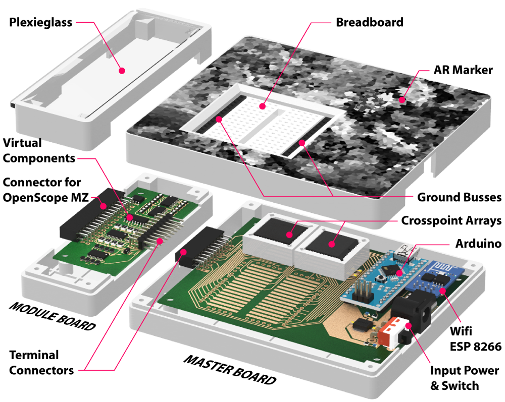 The short version is that VirtualComponent is essentially a dynamic breadboard. Holes in the same row are still electrically linked like in the classic breadboard, but with two AD75019 cross-point switch arrays and an Arduino in the base, it has the ability to virtually “plug in” components at arbitrary locations as selected by the user. So rather than having to physically insert a resistor, the user can simply tell the software to connect a resistor between two selected holes and the cross-point array will do the rest.
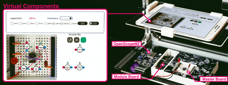
What’s more, many of those components can be either simulated or at least augmented in software. For example, by using AD5241 digital potentiometers, VirtualComponent can adjust the value of the virtual resistor. To provide variable capacitance, a similar trick can be pulled off using an array of real capacitors and a ADG715 digital switch to connect them together; essentially automating what the classic “Decade Box” does. In the demonstration video after the break, this capability is extended all the way out to connecting a virtual function generator to the circuit.
The whole system is controlled by way of an Android tablet suspended over the breadboard. Using the tablet’s camera, the software provides an augmented reality view of both the physical and virtual components of the circuit. With a few taps the user can add or edit their virtual hardware and immediately see how it changes the behavior of the physical circuit on the bench.
People have been trying to improve the breadboard for years, but so far it seems like nothing has really stuck around. Given how complex VirtualComponent is, they’ll likely have an even harder time gaining traction. That said, we can’t help but be excited about the potential augmented reality has for hardware development.


My $3 breadboards are sitting out on my hobby desk!,
Wow!
All I need is to install druffle, to compile shuffle, running on the babble framework, dependant on the grabble architecture, needing the fooble server, and gooble client, linked to a nuffle account, to enable puffle to fluffle the socksifier!
Or I can just plug the resistor in my old fashioned breadboard, but hey, whatever works.
Yeah… Also this is a microscopic breadboard, way too small to do any real work/testing. Of course, you are limited by those fancy switches, while you can do traditional breadboard at about any size…
It might have some use in education but beside this it seems pretty useless and overengineered.
It’s an expensive solution looking for a problem.
Lazy people using premade unreliable Chinese wire (vs hand stripped solid wire) is sad enough. They don’t need a cross point matrix to hook up a tiny breadboard.
If installing an app on an Android device is really this hard for you, ask your granddaughter’s son if he can give you a hand.
“…essentially automating what the classic “Decade Box” does”
Call me old-fashioned if you like, but I rather like the array of knobs on my classic decade box and the tactile experience of selecting a value.
AD75019s are over $20 each when bought in quantity. What that buys you is the ability to quickly reconfigure the breadboard.
The datasheet gives 150 ohms for the typical on resistance of the switches, so this will resemble connecting up a breadboard using resistors instead of jumper wires.
Interesting idea, but I’m dubious of the value.
And now we can have AR smoke leaving our components.
If any of this was truly simulated e.g. with Spice), then I could accept the “virtual” tag, but they’re real components connected together using crosspoint switches. Does that make other applications of crosspoint switches “virtual”? And for precision, high speed use, they can be difficult to realize complex designs due to layout issues that introduce signal crosstalk plus stray inductance and capacitance without careful layout design.
So, why not have an article on PSOC devices that incorporate uC, with analog and digital FPGAs, like those from Cypress and others?
And I have a rather nice 1/2 W, 1%, 7 decade adjustable resistor PCB (3.5 x 10 cm) using a “manual” crosspoint switch in the form of 0.1 in dual headers and dip jumpers in a very compact form, with less stray capacitance and inductance (although I have not measured that, so it’s conjecture) that came from China at a staggering cost of less than $5 (search for “7 Decade Programmable Resistor”) . But I have to admit that digital pots are way neater and a lot more compact, albeit with much less resolution (usually only 7 or 8 bits).
Seems like a lot more work and expense, not to mentions overly complicated, means more work troubleshooting. Just breadboard the parts, if you want a physical circuit. If you are just playing around, and don’t want to fiddle with parts, just do a simulation on the computer.
I think the idea is very cool, but the implementation will get bad results.
The cross point switch has rather high resistance (200 ohms) and high capacitance (25p). This is enough to influence a significant bunch of the circuits somebody might test on a bradboard.
Not to mention that you would need at least 5-10 of these for a decent size breadboard and that will still get you a tiny selection of components. An electronic potentiometer will give you a linear set of values, while in reality you probably use 4-6 orders of magnitude of resistors on the breadboard. There is no equivalent for capacitors. Or for transistors. Or inductors. Or LEDs….this will be extremely limited compared to even a basic kit.
Sounds like a weird way to re-invent an FPGA.
However, would be cool if there was a breadboard paradigm FPGA design environment, graphical breadboard with ICE, then prog it and run.
The analog world having some of the same advantages as the digital.
Ignore the breadboard. the cool thing is how they are doing the AR.
how do i get this up and running. I cant find any documentation.