If you like mechanical keyboards, you like switches. Historically, switches were weird, with strange capacitive rubber dome switches in Topre boards, buckling springs in the IBM Model M, and beamsprings in earlier IBM keyboards. This teardown of an HP signal generator has the weirdest keyboard switches ever. They’re being called pulse transformer switches, but they are the strangest, weirdest, and most complicated keyboard switch we’ve ever seen
Mechanically, these keys are mounted on a 1×5 plastic frame with a plunger that presses down on a (brass?) photoetched plate. Mechanically, this is effectively a metal dome keyboard that simply presses a springy bit of metal against a contact on a printed circuit board. That’s the mechanical explanation, the electrical theory of operation is much, much weirder.
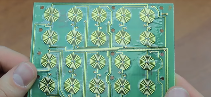
Electrically, this keyboard consists of a printed circuit board with two coils underneath each key. The circuit is wired up so two keys are ‘read’ at the same time with a pulse from a multiplexer. This pulse induces a current in the ‘sense’ coil of two individual keys which is sent to a comparator. If both keys are not pressed, the comparator sees a positive and a negative voltage which cancels out, meaning no keys are pressed. If one key is pressed, the metal dome shorts out the transformer underneath the keyboard, meaning only one voltage is seen by the comparator, and that key is registered as being pressed.
This is some crazy keyboard circuitry, and I do not say that lightly. There are ‘acoustic’ keyboards out there which consist of a row of keys striking a metal bar with an acoustic transducer on each end. By measuring the time it takes for the sound of a keypress to reach either end of the metal bar, a keypress can be registered. This is weird and expensive to build, and it’s still simpler than a pulse transformer switch. Check out the video below.


Sort of like the inductive version of a capacitive keyboard?
A long time ago the ribbon cables on my spectrum finally gave up, and I decided to move the whole thing in to an old terminal keyboard I had been given (think in terms of the Memotech keyboard/case which was available commercially)
The keys on that had a foam cylinder with a foil disc pressing against the PCB when the keys were pressed.
I just re-wired the matrix and was very disappointed when I found that the keyboard did not work at all. I then found that the foil discs were actually insulated, and were there to change the capacitance of the underlying PCB pad.
I tried to glue bits of aluminium foil on instead, to make it in to a conductive keyboard, but with pretty much no success, and that was pretty much the end for my Spectrum. (I had just started my degree course, I wasn’t short of other things to be doing)
That’s right. An inductive keyboard. Over the years, many different things have been tried, to eliminate the contacts in switches, especially for keyboard applications. The two biggest reasons for this are cost and reliability, and these factors interact – cheaper contacts tend to be less reliable. Since you usually need a PCB anyway, no matter what kind of switches are used, the best you can do is come up with a switch that a) doesn’t require contact, and b) can be incorporated into the PCB. The keyboard described in the article and capacitive keyboards are the only types I can think of that manage to do that.
The kicker here is that in 1971, the digital world was mostly built with bipolar transistors. This would have made capacitive sensing more diffiicult than inductive sensing, since measuring a small capacitance requires sensing voltage on a high-impedance input (which is simple today, with everything being based on CMOS), while sensing inductance (or inductively-coupled pulses) requires sensing a current on a low impedance input, which is what bipolar transistors are good at.
Just last week I came across Steel Series Apex Pro keyboard (via LinusTechTips youtube channel), which created a keyboard without an actual mechanical switch. It uses tiny magnets for each keys, and a hall effect sensor on the PCB (https://steelseries.com/blog/adjustable-mechanical-switches-104) They even lets you select the sensitivity to make the key to be feather touch to full throw. I don’t think having a 102 hall effect sensors feeding 102 ADCs scanning every 700 micro second was possible just few years ago..
Another interesting design is opto mechanical switch (https://www2.razer.com/au-en/razer-opto-mechanical-switch) which uses led in each key and a photo diode to detect the key press.
If it’s like this Compaq keyboard (I have two Wang keyboards too that have a similar PCB) then it’s indeed capacitive. And it’s NKRO. And that for 1982. When you try to probe the signals with a 10x probe, the keyboard stops working :(
I mean this of course: https://hackaday.io/project/7640-repairing-a-broken-compaq-portable-keyboard/log/25096-step-2-defining-the-problem
What you have is actually two capacitors, connected in series: one from the first pad to the mylar, and one from the mylar to the second pad. The capacitance between drive and sense pads is thus the series combination or half the capacitance from the pad to the mylar. The voltage pulse on the drive pad passes through the two capacitors and appears on the sense pad. i=Cdv/dt, so you sense a small positive current pulse, followed by a small negative current pulse for each drive pulse.
We did one of these from scratch on the Data General D200 terminal. A CMOS inverter drove one side and a 4051 mux and a Schmitt trigger on the sense line. Its main advantage was no contact bounce or wear. Disadvantages were static susceptibility and degradation of the foam. It was also wicked cheap (main goal).
Worked well, unless placed on top of a CRT, where the EMP from the flyback causes spurious characters to appear on the screen. I fixed that by timing keyboard scans to fit between flyback pulses (both the keyboard scan and the flyback pulse were timed off the main processor, so they could be phase-locked. Of course, if you put the keyboard on top of the *adjacent* terminal, all bets were off :-)
Holy cow, the Data General! Where I work (a federal govt installation with significantly less funding than most, because trees aren’t a constituency), we had a Data General system-mainframe and those fine old black screen-green type terminals well into the end of the 1990s. The IT department, which wasn’t called that, consisted of people who cut their professional teeth on punch cards and saw no reason to give up their god-like control of computing. Bu golly, if a mainframe was good enough for them, you certainly didn’t need those new-fangled things that could print a graph for publication. Why, there was graph paper and pens for that! You had to request a technical approval to get a standalone computer and printer that took months to process, and needed an upper level of management with hobnailed boots to push through. And came out of the unit’s pocket, of course.
The only reason they replaced them was Y2K, and then their choice for replacement was an IBM mainframe and dumb terminals (shared just like the DG terminals). They made the mistake of having PCs on the contract, intended for running screen reader or other accessibility software, but it was the camel’s nose under the tent, and all those people have gone the way of the dodo. It has taken a complete reorg/relocation of that part of our organization, and the hobnailed boots of the entire upper management, as well as congressional budget pinching to make IT sort of serve the mission, instead of the other way around.
There are a couple of other types of keyboards, which aren’t based on mechanical contacts, capacitance, or inductance. One is based on a piezoelectric film, such as poled PVDF. Theoretically, one may even be able to produce a “tactile feedback” by exciting the piezoelectric film, after a contact was sensed, thus producing a mechanical kick. Or, something like that.
So, I wonder what the wackiest idea would be that hasn’t been used yet?
Strain gauges in the springs seems fairly obvious, and a logical step fromt here would be strain-sensing optical fibre springs. If absolute resistance to electrical noise is important that could be useful.
Thermocouples in the key caps, to detect warm fingers?
Gene sequencers in the key caps to detect the _right_ fingers? (More practical, fingerprint scanners in each key cap)
Hall sensors must have been used? Accelerometers would work.
keyboards that only click and time-of-flight microphones?
Keyboards that each click at a subtly different frequency and fourier analysis?
Polonium crystals and neutron tomography?
I had a Microswitch keyboard from the late 1970s that used hall effect “switches”. I used it to replace the horrible “chicklet” keyboard on my Tandy Color Computer. All it required was some 10k pull-up resistors (one on each row or column – dont remember which), and it worked perfectly. Very nice keyboard; probably cost about $200 new, in 1970s dollars.
Hall effect keyboards are still sold new among the enthusiast crowd. not sure why they haven’t taken off. there’s infra red beam switches also in common use.
I suppose mercury float switches would be durable but I am not aware of their use in keyboards.
Mercury + Hall makes me think about reed relays, those would work too.
They do! I took apart a very old printing calculator when I was a kid, and the keys had tiny magnets in them to activate an array of mini reed switches.
I’ve seen keyboards made from reed switches, with a magnet on each key plunger. Expensive, but each reed switch could be replaced separately. This was on some Tektronix instrument – don’t remember the model.
Response time might be something.
“Keyboards that each click at a subtly different frequency and fourier analysis?”
Zenith did this with their “Space Commander” TV remotes in the 1960s. Yeah, vacuum tube receiver for this, on a separate chassis in the cabinet. These used a separate metal bar for each button, and the buttons had snap mechanisms that struck the bars, each of which resonated at a different ultrasonic frequency. I’m sure it would be tricky to get enough discrete frequencies for this, but maybe if each key struck two resonators, a DTMF-like matrix could be made. This have the advantage of requiring no power other than the user’s fingers, and be highly resistant to EMI. ‘Course, they don’t tolerate interference from other mechanical noise very well – on Grandma’s TV, it was possible to change channels and/or mute the sound just by jingling your keys. DTMF would help with this, though, provided the frequencies were not harmonically related.
ha…I had a roommate with one of those tv’s and remote. First time I came by with a vacuum cleaner the tv woke up and started changing random channels and volume….scared the crap out of me.
What? No reading the chemistry of each fingertip? Or the aura at each finger?
Laser interferometer? youtu.be/MUdro-6u2Zg
What surprised me the most in your video is that it is very ASMR ( https://fr.wikipedia.org/wiki/Autonomous_sensory_meridian_response ) . Indeed the author of the video speaks with an erotic voice and the sound of the machines makes the situation very sexual. :)
Microchip and TI (probably others too) have chips/peripherals in MCUs dedicated for inductive touch sensing.
I just had an idea for an even weirder non-contact keyboard: Each column of switches has a light/laser under it, pointing down the column at a photocell. Each key has a filter to dim the light double the darkness of the previous one. The maximum number of keys per column (or per row if you do it horizontally) would be determined by how many bits your ADC can handle. Voila! Light-based N-key rollover!
You could simplify this by placing a cheap photocell under each key and have each pressed-down key diffuse a small portion of the light and pass the rest through
Okay, I’ll play:
1) put a laser diode at the left end of each row of keys, pointing to the right.
2) mount a 45 degree mirror on each key plunger, that is pushed down into the laser beam when the key is pressed, that reflects the beam toward the top of the keyboard.
3) put a photodiode at the top of each key column.
This doesn’t require any active devices for each key; just for each row and each column. It’s not technically n-key rollover, but unless you’re pressing a key and the one above it at the same time, it can practically be n-key.
With reflectors on both sides of the key base N-key rollover becomes an implementation of the game “Black Box” https://en.wikipedia.org/wiki/Black_Box_(game)
Yeah!
Hey! That’s not a bad idea! If you used a partial mirror (…or even just a piece of clear plastic), only some of the light would hit the photodiode and the rest would pass through to be available for other keys. The issue would be that the signal from the photodiode is analog, not digital, and would require additional circuitry.
Back in the early 1980s Smith Corona introduced a line of typewriters called the Ultrasonic series. These used a unique acoustic reed keyboard, where each key would strike a reed, and the frequencies generated would be analysed by a microcontroller to determine which key has been pressed. A bi-directional computer interface was available.