When debugging ordinary low-voltage circuitry, you’re pretty safe: unless you have some really power-hungry devices that need a ton of current, there aren’t that many truly bad things that can happen, so you can take a lot of liberties with electrical-safety rules. With mains-powered devices, you don’t have this luxury, and a lack of knowledge, sloppy work practices, or simple mistakes can cost you — and your project — dearly. While you still need to know what you’re doing and use the requisite caution, [Yann Guidon]’s latest project — and entry in the 2019 Hackaday Prize — a mains protection box, might keep simple mistakes from becoming a disaster.
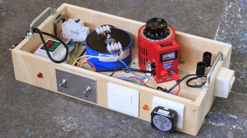
There are a number of precautions you can take when working with mains power. We’ve all used the simple in-line power strip so you can quickly switch off the current, but [Yann] has included a number of devices that can be configured in different ways to experiment with mains-powered devices safely. Built into a sturdy open-topped wooden box with carry handles, the project evokes the traditional breadboard in appearance and functionality. A number of different devices are included, which could be re-configured into different topologies if needed.
[Yann] included an isolation transformer, which can be useful not only for protection against shock in case of accidentally grounding, but also for noise suppression. There is also a variac, which allows the output voltage to be adjusted over a wide range for testing. Of course, circuit breakers are a must, and current and voltage meters keep you informed about what’s going on. A big, easy-to-access switch cuts the power quickly when needed.
The (maybe) final touch is an adjustable output current limit, which is still a work in progress. Built around a current-monitoring relay and a DPDT relay wired as a latch, this allows the output to be disconnected if it draws more than a specified current, equivalent to between 10 W and 100 W. This is the perfect thing for initial testing of new projects.
So, if you’re thinking of working on mains-powered projects, have a close look at what [Yann] has assembled, and learn proper safety procedures before you begin. One place to start is with a great series by our own Jenny List about mains safety: part one and part two. Stay safe out there!


You can also use an incandescent light bulb in series as current limiter, works perfect.
You cant use an incandent light as a current limiter if you touch it with any of body parts.
It has a working recistance of 29 ohms.
Make the math what that does to the voltage and make sure to add your (wet) skin resistance.
Looks like there are two bulb sockets in the box.
They indeed act as medium resistances and loads.
I have found several incandescent low-power light bulbs, with high resistance, to act as series protection/PTC.
2 switches control the operation.
I use the incandescent bulb trick in my AC line safety test jig. Learned this trick back in the 70’s when I started working in a TV repair shop. In my fixture the bulb is socketed so I can swap in different Wattage bulbs depending on the current I expect to draw.
Years ago I coupled an Isolation xfrmr to a variable xfrmr to isolate the output.
Hmmm, maybe I should add a Ground Fault Interrupter to it as well.
Are you really expecting current in a ground fault when you have the isolation transformer in circuit?
This is the sort of advice that’s needed only once. Unless you’re a 15 year old boy and then maybe twice. (I was that 15 year old boy once)
While I know what you mean, that “only once” seems to come up at least twice a year for me. There needs to be a word for the category of gear that you always wish you had at the time, but then you think you’ll never need again. Until the next time.
Assuming that I live longer than a couple more years, it’ll be worth making. And just having an isolation transformer could increase the odds of me living a couple more years…
I wish you stay with us a “bit more” than two years, Elliot :-)
keep safe !
Why you add a transformer in the first place is to remove any reference to physical ground.
exactly :-)
Those exposed screw terminal blocks mounted high-up and carrying mains are not going to help anyone work safer. Maybe that would turn out to be the “final touch” referred to in the article.
You would operate the “box” from the side, where the switches and plugs and pilot lamps are located.
Like a bench power supply or oscilloscope.
The box will be located at about eye level, so access from above is unlikely during normal operation, and can be prevented with more wood but it’s already getting overengineered :-P
Operating the Variac would require access from above, and might happen fairly often.
makes sense…
but the live wires are not directly touchable (you’d have to probe with a screwdriver) and I have to solve other problems first, in particular the insane inrush current of the iso transformer :-D
that large coil always trips the circuit breaker when I power it on…
I have used this configuration with the light bulbs for over 40 years, it works great. I have an assortment of bulbs with switches I can connect or disconnect each as desired. The box has both voltage and current meters. I used a 750VA machine control transformer and switch the secondary to get either 220V or 440V. The variac powers the transformer allowing adjustment from about 0 to 600V. The current limit is not for control but to simply prevent catastrophic failure of the DUT.
Please document/publish your own system !
An isolation transformer has its downsides as well as having its benefits. The biggest problem is that it prevents a GFCI (known as RCD in some countries) from detecting a fault and cutting power when an errant connection is made to ground.
Consider a mains-powered device with its hot and neutral wires. Imagine it plugged in with no GFCI and no isolation transformer. What happens if you are standing on a good ground and you touch the hot wire? You get a strong jolt, potentially injurious or lethal.
Now change the outlet to one protected by a GFCI and touch the hot wire again. The GFCI detects an imbalance in current between the hot and neutral and cuts power immediately.
Now plug the device under test into an isolation transformer, and plug the isolation transformer into a GFCI protected outlet. Touch the hot wire and nothing happens. The isolation transformer prevents a complete circuit from being made, and it also prevents the GFCI from seeing any imbalance in current, since the GFCI is only driving the primary coil of the isolation transformer, and no imbalance exists there.
Either device prevents a problem when only one point in the circuit is touched. The difference between the approaches happens when a second point in the device under test is also touched. With an isolation transformer, a shock results. Without an isolation transformer, the GFCI was able to cut power before the second point was ever touched.
My point isn’t to say that an isolation transformer is bad. There are certainly situations where it can improve safety. But it always prevents a GFCI from detecting any fault that happens downstream of the transformer, and there are situations where a GFCI’s ability to cut power improves safety, sometimes even more than the isolation transformer.
Be careful, and understand how these things work before poking around with mains power.
Yes there are many things to keep in mind when dealing with these devices.
The whole point of this “box” is to put all the devices in a single place, easy to rewire and reduce clutter or danger on the workspace.
Would it be possible to add a GFCI on the secondary side of the transformer. Only cutting the power to the secondary side so you don’t have to find your switchboard and reset the whole household ?
it is my understanding that GFCI detects and remedies ground faults. The isolation transformer “floats” the secondary so there can be no significant current to ground. GFCI would be useless and there is none in this box, only overcurrent detectors. I made the mistake to put a 2A one because it sounded “enough” yet I didn’t account for startup current…
Now, cutting the secondary side is a good idea, but there are already plenty of such features : the output is enabled by a switch AND a parallel push-button (sort of “dead man’s switch”), I design an active overcurrent detector, etc.
But the primary side still creates a crazy inrush current when plugged in. That’s the only problem so far…
PS: my tests show there is no ground connection on my mains network so GFCIs might not even work.
However, floating the output is still required if I want to probe mains with a ‘scope.
As someone already mentioned in the project discussion, there are “slow” circuit breakers, better for inductive loads, as they ignore the large inrush current. They trip only after a few seconds of constant overload.
I like the concept, and this appears to be a no bad implementation, but two GFCI units would improve safety a lot: one at the input, and the other between the ISO and the variable autotransformer. The second need not have a ground connection. This will protect against a variety of faults other than grabbing both leads with your hands. Protection from that is also possible, but MUST be done right, so I will not get into detail here
A GFCI on the output of an isolation transformer doesn’t help. It only detects an imbalance in current between the hot and neutral legs, but both ends of the transformer’s secondary are guaranteed to have the same current.
Now, if you ground one side of the transformer’s secondary before the GFCI, you would allow that GFCI to do its job. But why use an isolation transformer in that case?
There is no GFCI, just a usual overcurrent breaker.
The isolation transformer prevents GFCI from working, at the output, and the input is quite minimalist so there is no need to protect from ground leaks.
However surge absorbers are useful, with all those huge inductors !!!
Actually, it does help. On the output of the iso, the two principal risks are undetected fault to ground (direct or indirect, including failure of isolation) ANYWHERE in the circuit, and presenting risk for contact to any part of the nominally isolated side, and contacting both current carrying lines on the iso side. The GFCI will protect against injury due to the former, as it will lead to an imbalance that will trip the device. Failure of isolation is not uncommon, which is why we HiPot test.
It is also possible to have it protect against the latter, but, again, done wrong is more dangerous than nothing at all, so I will not go into detail.
In industry, and in the home, more people are injured by faulty isolation practice (“I thought it was disconnected’, ‘I didn’t know there was a second feed’, ‘I didn’t know there was someone working on the circuit’, and so on) than by any other electrical issue.
Your last argument is interesting :-)
That’s why I have installed pilot lights and LED voltmeters to clearly show what’s going on in the box.
This time, there is only one error :-P
“but also for noise suppression” => no, noise suppression is with LC filters ;-)
I have put surge absorbers but noise was not a concern.
I don’t even think I mentioned noise in the project page…
However my thought was to be able to plug a ‘scope without grounding shorts or things like that.
But why leave the box open with all the wiring exposed..?
because you may want to re-wire or probe wires ?
The box is a prototype lab equipment, meant to reduce clutter and risks on the workbench, operated from the side and only the variac is accessed from the top.
it’s not meant to be manufactured or operated by non-technicians, and you don’t want to have to open/close/open/close it all the time.
Gread job and very interesting! I don’t get all the naysayers on this site.
Thanks S :-)
naysayers are just how Internet is…
and you never know if one of these “nay”s might really be a good advices :-P
but for this, people should first look at the project itself,
and not rely on the journalistic description ;-)