Back in the day, all of your music was on a shelf (or in milk crates) and the act of choosing what to listen to was a tangible one. [Michael Teeuw] appreciates the power of having music on demand, but misses that physical aspect when it comes time to “put something on”. His solution is a hardware controller that he calls MusicCubes.
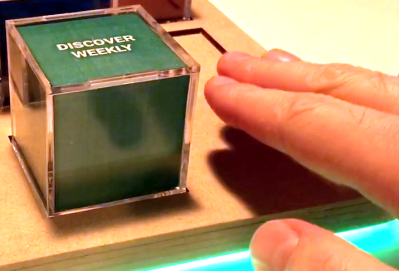
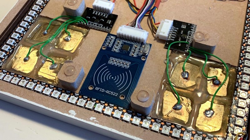
This is a multi-part project, but the most recent rework is what catches our eye. The system uses cubes with RFID tags in them for each album. This part of the controller works like a charm, just set the cube in a recessed part of the controller — like Superman’s crystals in his fortress of solitude — and the system knows you’ve made your decision. But the touch controls for volume didn’t work as well. Occasionally they would read a false touch, which ends up muting the system after an hour or so. His investigations led to the discovery that the capacitive touch plates themselves needed to be smaller.
Before resorting to a hardware fix, [Michael] tried to filter out the false positives in software. This was only somewhat successful so his next attempt was to cut the large touch pads into four plates, and only react when two plates register a press at one time.
He’s using an MPR121 capacitive touch sensor which has inputs for up to 12-keys so it was no problem to make this change work with the existing hardware. Surprisingly, once he had four pads for each sensor the false-positives completely stopped. The system is now rock-solid without the need to filter for two of this sub-pads being activated at once. Has anyone else experienced problems with large plates as the touch sensors? Can this be filtered easily or is [Michael’s] solution the common way to proceed? Share your own capacitive touch sensor tips in the comments below!
Want to get a look at the entire project? Start with step one, which includes a table of contents for the other build logs.


Impedances versus Ohms
Hackaday has a decent comments section on this fail of the week regarding capacitive sensing.
https://hackaday.com/2017/06/16/fail-of-the-week-museum-buttons/#comments
Someone there has linked an app note by Cypress which may offer insights.
The MPR121 is powerful at tracking this kind of issues. It has embedded four-steps filters, the ability to adapt the charging times of each plates to match the electrode capacitance, and a myriad of parameters to adjust. A look at the documentation could help !
Also, the most complete library I could find for it is the BareConductive one.
Not particularly familiar with this new phase of capacitive-touch-sensing-everywhere, but seems like it would be sensitive to things like AC line noise, walking-by antennae [humans], wind-gusts, tea-kettles , candles, etc. AND, noise from nearby circuitry…
Back in school, we did capacitive-sensing with two separate plates, splayed-out in a single plane, one driving and one sensing… the electric field wrapping between them in a semicircular-fashion, “fringing”, and an object placed-atop, then, would act as a changeable dielectric. Because of the two-plate/drive-sense nature, frequency-dependent sensing was possible, filtering out external noise, etc. Also, filtering depending on the dielectric properties being looked-for. [E.G. water vs. paper, etc.]
Of course, that takes a lot more circuitry and analysis than, likely, these multi-channel single-plate systems provide…
Most-likely these single-plate-ers work by charging the plate then measuring the time it takes to discharge. Water nearby [a finger] attracts more charge than air, so the plate takes longer to discharge.
Very different systems, but there is one plausibly-related factor that comes to mind: placing another plate nearby may cause fringing e-field effects, (parasitic capacitance between sensors, which are *also* drivers) causing the separate sensors to essentially achieve some sort of steady-state resonance (especially, say, if one nearby plate is charging while another’s discharging) that overpowers the ‘noise’ that caused false-positives, before…
Or, yahknow, it could just be that the plate is so large that the charging-system was having a tough time… maybe some beefy power-rail decoupling capacitors would help. Or that the discharge-time-measurement system was near the maximum e.g. 0xfff9 ticks, on-average… wrapping back round to 0x0000 on occasion. [Wait, wouldn’t it be opposite for a false-positive? Fingers *increase* capacitance…].
Regardless of the cause, I’m quite surprised just how common these systems have become, especially amongst cheaply-designed products and hobbiests… I’d surely have predicted that the range of characteristics/environments necessary for these essentially drop-in systems to function reliably would’ve been quite small… yet they seem to be all around, proving me wrong.
Weird thing is, the technology is so simple it could’ve been this-common as soon as the 555 came out, decades ago. And, decades ago, it was in the hobbiest literature [e.g. Mimm’s]. And, even in those days it would’ve been cheaper to mass-produce than mechanical pushbuttons… makes me wonder what changed.
“AND, noise from nearby circuitry…” Like the RFID sensor right next to them!?
Or the 800kHz LEDs, lol
You need a ground surround for each cap pad to reject common noise. Otherwise you will always get stray triggers.
The MPR121 has a continues calibration routine which should reduce the false positives. I have found another big improvement in this chip (and this works in general when using cap-touch IC’s):
Give them their own local LDO this will reduce the supply voltage noise (make use of the LDO’s PSRR).
I hope this solves the false positives for this fellow Dutch tinkerer.
“Groeten” Emiel