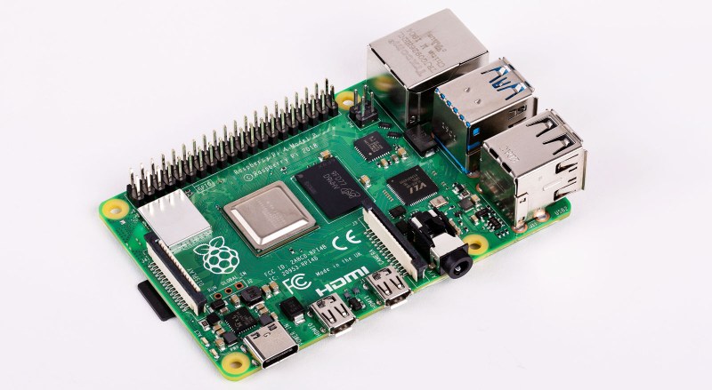
The Raspberry Pi 4 has been in the hands of consumers for a few days now, and while everyone seems happy with their new boards there are some reports of certain USB-C power supplies not powering them. It has been speculated that the cause may lie in the use of pulldown resistors on the configuration channel (CC) lines behind the USB-C socket on the Pi, with speculation that one may be used while two should be required. Supplies named include some Apple MacBook chargers, and there is a suggestion is that the Pi may not be the only device these chargers fail to perform for.
Is this something you should be worried about? Almost certainly not. The Pi folks have tested their product with a wide variety of chargers but it is inevitable that they would be unable to catch every possible one. If your charger is affected, try another one.
What it does illustrate is the difficulties faced by anybody in bringing a new electronic product to market, no matter how large or small they are as an organisation. It’s near-impossible to test for every possible use case, indeed it’s something that has happened to previous Pi models. You may remember that the Raspberry Pi 2 could be reset by a camera flash or if you have a very long memory, that the earliest boards had an unseemly fight between two 1.8 V lines that led to a hot USB chip, and neither of those minor quirks dented their board’s ability to get the job done.
Mistakes happen. Making the change to USB-C from the relative simplicity of micro-USB is a big step for all concerned, and it would be a surprise were it to pass entirely without incident. We’re sure that in time there will be a revised Pi 4, and we’d be interested to note what they do in this corner of it.


Or, they could have just used a standard barrel jack and got rid of usb* for power input.
Well there has always been an alternative. I wonder if you can still just input power on the 5V pins like you could with the previous Pis. If you can do that you can make pretty much any charger work.
That is how the PoE HAT works and the 4B is compatible with that, so it must still be possible.
One of the features of the new board: “5V DC via GPIO header (minimum 3A*)”
source: https://www.raspberrypi.org/products/raspberry-pi-4-model-b/specifications/
It’s not a new feature.. I’ve been running my PI’s on 5V DC via GPIO since version 1 :)
Technically he/she never said it was a new feature
I’m not sure about the tech specs but I’m almost sure they wouldn’t list it as a feature if they didn’t change something.
Maybe in this new version of the board the 5V lines don’t bypass some filtering and protection circuitry that was available for the usb input only on previous versions…
Yes, before the RPi 4 you ‘could’ input 5v through the GPIO header, ‘but’ it bypassed a polyfuse, and put your Pi at risk. The GPIO for those models is 3.3v tolerant, not for a constant 5v. If it worked, it worked…but wasn’t guaranteed to. What Blamoo posted, was the specifications of the ‘new’ RPi4, which ‘now’ handles a 5v input, at a ‘minimum’ 3A. It now officially supports powring the Pi through the GPIO. That’s definitely a ‘new feature’.
“5V DC via GPIO header (minimum 3A*)”:
The only way to ascertain whether this actually means ‘supplying’ the Pi4 board directly for its own power requirements, or ‘delivering’ 5V power out to an external device ‘from’ an already powered board, is by the little asterisk. This asterisk this refers to a minimum value of an external transformer PSU.
If we consider the asterisk as accurate, then it indicates attaching a ‘good quality’ power supply to this pin. If the asterisk was not there, it would only indicate that 5V is present from this pin, perhaps for use by other devices.
I would presume regulation and protection is being by-passed by connecting power feed here to power the board. (!?)
USB C on the Pi 4 is also OTG, which will be hard to achieve on the barrel jack.
The power supply connector should be separate from USB-OTG connector anyway, at least in this case…
Unfortunately it isn’t a full dual role device (DRD) or OTG connection (was looking for details on that when i found the mistake) it is just a client device (UFP), Still very useful for linux gadget modes though (assuming you connect to it with a non e-marked cable due the issue).
dtoverlay=dwc2,dr_mode=host
Well a barrel jack would certainly work and be more elegant. But Raspberries are basically disposable SBC’s so the designers cut corners wherever they can.
Frankly it’s ridiculous though. Then again the Rpi was one of the few boards released with no ability to mount it to anything.
i don’t think i ever powered a pi through the usb port. ive used atx power supplies and ubecs and none of those have a usb port.
Tip and ring connectors aren’t particularly standard: not only do diameters vary but polarity too. And I worry sometimes about the power loads people put on the tiny ones. Using type C lets you run power up to 100W, and increases the probability someone will have a charger lying around (if, of course, you implement the standard properly!).
In exactly what way is a barrel jack standard?
I have seen them in a variety of sizes, polarities and voltages. With USB you have far more standardisation than any barrel jack.
If they don’t bother follow/read the spec (missing resistor), then it is really a design issue.
I wouldn’t bother Using USB charger the VUSB voltage can vary greatly (4.4V – 5.25V as per spec under load). A wallwart with a regulated output would be a lot tighter.
There’s also the whole problem of the USB-IF suffering from not-invented-here syndrome. They didn’t include a charge standard in the original USB specifications, so manufacturers, en masse, settled on using resistor values, between the data pins, to indicate the available current. This was a case of an “industry standard” not being a standard from a standards body, and the USB-IF wanted to remedy that. Because of their bad case of not-invented-here syndrome, instead of adopting the industry standard, they created their own contrary standard.
USB C has implemented some of the functionality that USB-IF never implemented in USB A and USB B connectors, and again did so in a way contrary to most chargers on the market, so if you have a 3 amp USB 2.0 charger that you were using with the USB Mini B connector on a Raspberry Pi 3 or earlier, to use it with the Raspberry Pi 4. you’ll need a USB A to USB C cable that adapts the non-USB-IF industry standard to the USB-IF standard for USB C. This is done by adding a 10k pull-up resistor on the USB C connector’s configuration pin, to tell the USB C device to draw the full 3 amps that the charger can output. The USB-IF only allowed a much lower maximum current, so if you only use cables complying with their specification, the Raspberry Pi 4 can’t run from a charger with a USB A 2.0 port, even if they’re electrically compatible.
Yea, fuck that. You’d have to make some kind of hack or something to make it work. I mean, who does that?
USB has been a mess since the very beginning. USB 1 had two separate (and incompatible) host controller interfaces.
Apple, Samsung, several others who each came up with their own way to tell their devices what sort of charger they’re plugged into so the device knows what amperage it can draw. Quite annoying when my Samsung phone will only pull 500ma or less from a “2 amp” charger.
It’s also suffering from refusal to learn. After the connector fiasco that was SCSI, these morons created USB… with a connector that can only be oriented by trial and error, and has proliferated into at least four different connectors… with “micro” being a flimsy POS that should never be used, let alone for power.
I wonder if the new pie still goes down if you accidentally touch 5v and 3.3 v rails :-/
It probably will as you should never connect two different power rails together.
Try this in a PC with the 12V and 5V rails. Something will probably break.
Connect 5V to a GPIO pin of the Pi, you will probably also break things.
In other words: please be careful connecting stuff to a powered on Pi.
Spoilers: nope.
This is possibly also a cost issue. Resistors are cheaper than an actual USB-PD controller and suitable protection. True USB-PD really isn’t a simple affair.
For you kids playing at home, if you don’t mind throwing a little money at it (~25usd), cypress make some interesting parts in this space. Check out the cypress CY4533 for a handy benchtop power supply when used with a decent high wattage USB-PD capable charger:)
TI and some others also make relevant parts.
If you want to both source 5V or more and sink more than 5V things get a lot more complicated. On semi seems to be the only supplier of suitable high side drivers for this unless you want to roll your own, and protection for the bus is still a pain.
“For you kids playing at home, if you don’t mind throwing a little money at it (~25usd), cypress make some interesting parts in this space. Check out the cypress CY4533 for a handy benchtop power supply when used with a decent high wattage USB-PD capable charger”
I swear I’ve already seen Chinesium equivalents of that to the tune of 8 to 10 US Dollarydoos, they even seem to either be using IC’s meant for USB-PD duty from respected manufacturers (or clever clones yet again).
But I still haven’t found easy to use and affordable boards for the other end (supplying the USB-PD power instead of consuming)
It’s certainly possible. Actually the $25 that I mentioned was for the eval kit, so the cypress part itself is likely less.
But yeah, the other end is less common. Likely because they probably have to do some sort of certification to make things that plug into walls. There are definitely reference designs out there though.
Not to keep plugging cypress, but google “CCG2 24W Power Adapter Reference Design” and you should find some stuff. For other reference designs of theirs google “USB Type-C and Power Delivery” click the top link and then “reference designs”
How about a gizmo with a make USB Type A on one end, female USB Type A on the other, and in between smart circuitry that detects what kind of device is plugged in and the power output capabilities of the power source, then configures itself to hook things up with as high of power transfer as possible?
USB-C standard looks better in this regard as USB-C cable provides information about itself (what power and capabilities it is rated for) and source is well, USB-PD…
The problem is not that resistors are cheaper than an actual USB-PD controller.
The problem is that to meet spec there should be one resistor per CC line, not one resistor shared between the two.
This will be a major headache for users, because people who make a point of NOT having cheap/crappy cables lying around like myself will get hosed by the fact that the Pi insists on being driven by a cheap/crappy cable.
Gotcha, I guess correctly setup resistors are fine if you all need is 5V at 3A.
Yeah, if you need more than that on a Pi, you probably should be giving it supplemental power via the GPIO headers.
In this case, cables that are *capable* of delivering 5A won’t work at all. Cheaper cables that *can’t* deliver 5A in a standards-compliant matter will work.
This is a problem because:
1) It’s damn near impossible to tell the difference between a 5A-capable e-marked cable and one that is not visually
2) It means that to power the Pi, you need to keep around cables that potentially *can’t* power other things.
While I have no devices currently that need 5A from an e-marked cable, I’ve been making a point of buying the “better” e-marked cables so I don’t have massive grief when I do need them (see 1 above) – but if I want to power a Pi via USB-C, I need to avoid e-marked cables.
(The workaround solution may be to only use A-to-C cables for power, which are fundamentally not e-marked.)
I’ve connected a 4Gb Pi4 to a PD charger capable of charging a PD Pocket just fine … and guess what? Yellow Lightening bolt flashing as usual…
Seriously, if they only designed to spec with decent chargers rather than pushing their own as ‘this is what we support’
What cheap crappy cables work with decent chargers then?
The Pi4 isn’t doing PD. The charger has to provide 3A _without_ PD negotiation. Not all PD-capable chargers will do that.
Good grief, just how much current does this super computer take!
(I think it is pretty cool)
At this point I’m almost expecting someone to conjure up a board with a standard 5.5/2.1 mm barrel jack in one end with a input range from just above 6V to probably 18V and a stable 5.1V 3A output (as long as it’s getting enough current at input) banged out of a USB-C plug.
If conjuring a board like that, it would be easier/better to just use the gpio pins to feed the board, leaving the usb-c plug alone.
It’d be a more modular and quick connect/disconnect approach and also enable use of original case and/or not “disturbing” current shield stack.
Though I didn’t account for potential sideways mechanical load of the Pi’s USB-C connector with such a inevitably sized thing dangling out of it.
That’s actually a bigger buzzkill for that idea.
But why didn’t they just make the Pi (‘s) correct, and simply have a decent on-board power supply accepting a 6-18V (approx) range, so it could be powered by anything, even a car battery.
Oh yes, blah, blah, blah it would increase the price for the oh-so-poor students, but that is only at sort of NIMBY consideration, as there now is a requirement for a more expensive PSU instead, or home brew solutions, if one want battery powering.
There is a lot of potential in the Pi, but why can’t they make it correct, also so that the connectors are only at one side etc, etc.
And it could come in a big metal box with a blu ray drive, and a hard drive, and room for a high power graphics card. Maybe you’d be able to change the RAM and the processor too!
Nonsense.
Nobody are talking about converting the Pi to a full blown PC, but simply minimising the risk of corrupting it by providing to high a voltage, or reversed polarity.
And for tinkering purposes (and the tons of Pi sold, typically used for embedded purposes, paying for the show, so we can brag about we are soooo goood, and doing it for the kids) it makes sense to make it more robust and reducing the spaghetti wiring.
Nobody talks about converting the Pi to a full blown PC, but simply making it more robust, so it can accept a wider voltage range, and not it vulnerable to wrong polarising – that makes totally sense for a board used for tinkering.
Could someone please. ;-)
There is the MoPi 2 hat – https://pi.gate.ac.uk/pages/mopi.html
Although it’s more about very flexible power options – e.g. a variety of different batteries and things like solar, as well as DC power – 6.5V – 24V input range. And it would be bring your own barrel jack
Tooting my own horn a bit, but it seems relevant to the discussion. Just checked and verified that my LiFePO4wered/Pi+ (https://hackaday.io/project/20909-lifepo4weredpi/log/165305-raspberry-pi-4-compatibility) seems to work fine with the Pi 4 and I didn’t notice any low voltage warnings during my testing. Feeds solid 5V through the GPIO pins, you can power it with 5-20V (even solar panels), it adds an on/off button with clean shutdown and has battery backup for UPS functionality. Plus many more features.
If course it costs more than a standard wall wart but it’s often worth it to have proper power management!
I’ve found many of those generic USB chargers to be lacking in power delivery. They claim a 2.1 amp output but the voltage starts to sag when you approach 1.5 amps. By the time you get to 2.1 the voltage has fallen to 3.1 volts. I wont go into the electrical safety hazards that some of them are here.
If the RPi4 is using the Rd pulldown resistors for USB-C CC1/CC2 signalling (intended by the USB-C spec to support connection with non-USB-C hosts or devices), then the power source (USB-C charger) is NOT required to provide more current than the USB base specification, which is 900 mA. The charger MAY choose to advertise the availability of 1.5A or 3.0A, but is not REQUIRED by the spec to do so. A charger that only provides 900 mA for legacy devices is a perfectly legitimate standard-compliant charger, even if it is rated for 3.0A, because it can require USB PD negotiation to enable the higher current. PD negotiation is accomplished by using the CC lines for a protocol handshake, rather than just having pulldown resistors.
If the RPi4 uses Rd pulldown for CC1/CC2 signalling, then they MUST have two Rd resistors, one on each CC line. You can test this by taking a USB-C charger that does work with the Pi4, and flipping the USB-C cable. If it works in both orientations, then they have installed both resistors.
What they have done is to connect the two CC lines together so that they can use a single resistor, this means it will still work in both orientations if the cable only connects to one of the cc lines. There is also a line going from the cc detection pins to an analogue input on the chip so it looks to have the capability to check the available “Type-C current” power.
Interesting. USB Type-C cables are absolutely REQUIRED to only pass one of the two CC lines end-to-end. However,, an active cable may use both from one end internally, so both CC lines on the Pi sharing a resistor will make active cables unhappy. (They’d be unhappy for other reasons as well.) Also Type C devices with a captive cable might not like it, but there’s no reason to plug such a thing into the Pi Type C port.
A single (shared) Rd resistor is *never* OK. It’s not just “active” cables that will be an issue. Any SuperSpeed or 5A cable is requires to have E-Marker silicon that indicates the cable’s manufacturer and capabilities. This E-Marker will have an Ra resistor of 1K to ground in the same pin slot but on the opposite side of the plug from CC.
If you bridge CC1/CC2 on a receptacle, then that 1.0K Ra provides another path to ground, which substantially stronger than the usual 5.1K Rd pulldown. The result is that the sink (RPi) cannot determine what the source’s capabilities are.
This would result in source current detection on the RPi 4 being incompatible with Type-C chargers when used with a high-power charger cable, or a SuperSpeed cable.
Exactly. This write-up seems to cover this RPi4 problem and the missing resistor in detail:
https://www.scorpia.co.uk/2019/06/28/pi4-not-working-with-some-chargers-or-why-you-need-two-cc-resistors/
BTW – I hope this post makes it. The new comment system here on HaD is not reliable in my experience. Sometimes new posts just vanish, even if I try to repost them. At other times the posts work.
5A cables are ALL active (electronically marked). A USB power sink is not allowed to use more than 3A unless it has verified through PD negotiation that the cable and power source support it.
SuperSpeed doesn’t require active cables, except possibly if they are long. Even a long SuperSpeed cable that buffers the high-speed cables doesn’t have to be electronically marked, so from a USB-C PD perspective, it can still be a passive cable. SuperSpeed cables that are passive (not electronically marked) can work fine with a single Rd resistor; the Rd resistors have nothing to do with SuperSpeed. That’s totally irrelevant to the RPi4 USB-C power connecor tthough, as it doesn’t use ANY of the USB data lines.
I’m not arguing that a single Rd resistor meets the USB spec; obviously it does not, and it was stupid for them to save a tenth of a cent by not using two resistors. However, it will work fine with any standard-compliant passive cable, because such a cable by definition only connects to one of the CC lines, never both. Only active cables connect to both and are problematic with the RPi4.
Whether any particular USB-C charger works with the RPI4 is another matter. A USB-C charger is not required to provide 3A unless PD negotiation occurs, and the RPi4 cannot do PD negotiation. In practice one would expect a USB-C charger that can provide 3A with PD negotiation to provide it even without PD negotiation, because they would actually have to add circuitry to the charger if they wanted to prevent that.
You guys go know that the official one is only 8 euros, right? All your negative feelings could be solved for the cost of a McDonald’s menu :-)
While creating new problems?
B^)
The problem is the official power adapter is out of stock, plus the shipping time and cost.
Something that I just considered : If I have a 5V 5A power supply, I cannot just adapt an usb cable to connect to it, right ? I will need a usb-c supply capable of those power negotiations, isn´t it ? Maybe a notebook power supply.
That is, considering that something prevents from connecting power in the gpio pins …( like a case, shield is in the way, etc ) ..
Your 5V at 5A PSU is fine. You don’t need a special USB-C PSU or have to support USB-PD.
IMHO the pi’s have a long history of hardware incompatibility. The first ones were very picky about the power supply you used and running them for a long time or doing anything that took a little burst of current would reboot you if you were lucky or just crash you if you were not. They were also notoriously picky about the sd card you used in them, and it was doubly bad because SD cards were not the inexpensive throw away pieces they are today. I am not sure if the pi is a driving factor in the sd card and power supply market or just a hanger oner who is benefiting, but as much as I don’t like the pi’s, except for places where they really belong, the cost of deploying one has dropped significantly with the proliferation of low cost USB supplies and micro sd cards.
I ran through the same problem one week ago, with a small lamp using 6 5050 leds, intended to run on a power bank. It turns out that on my power bank the current draw is not enough to turn it on, while on every other I tested it’s ok…
The road to a working product, even simple as six leds and three resistors, is a though one. :)
These various issues with different Pi versions indicate the hardware developers aren’t really very good at their job. They repeatedly make simple errors like this, then clearly don’t prototype and test their designs before releasing them.
This stuff isn’t that complicated. Not to say its easy, but a bit of due diligence goes a long way.
My pi has now arrived so I have been able to do some tests. My blog post linked in the article has been updated with the info as well.
I have checked and both the CC lines are wired up as in the schematic with only one CC resistor rather than two. I have checked several power supplies with and without e-marked cables (a macbook pro charger, Pixel3 charger, Office electrics desk charger). All the chargers did not power the pi when used with the e-marked cable provided with the macbook charger. when used with a non e-marked cable all the chargers powered the pi.
Hi, nice article, you do, however, make much use of the word ‘charger’ and yet you aren’t charging, I came here by way of searching for a Pi charging scenario, not just a power supply. In your article, when I re-read it I replace the word ‘charger’ in my mind with ‘power supply’. Sure, some power supplies are used in a role where they charge, but that’s not the case here. Just terminology, keep up the good work!
This may be a silly question but I had that on my mind for quite a while, I have an ATX power supply on my table that I use to power some devices, if I hook up an USB connector to the 5V and plug in a USB type C cable can I power the Raspberry PI 4 that way?
With Pi3 I quite frequently used a phone battery pack to make my Pi portable.
Has anyone tried this with with Pi4? Are there USB-C-ish issues or will it just work?
Any recommendations on battery pack?