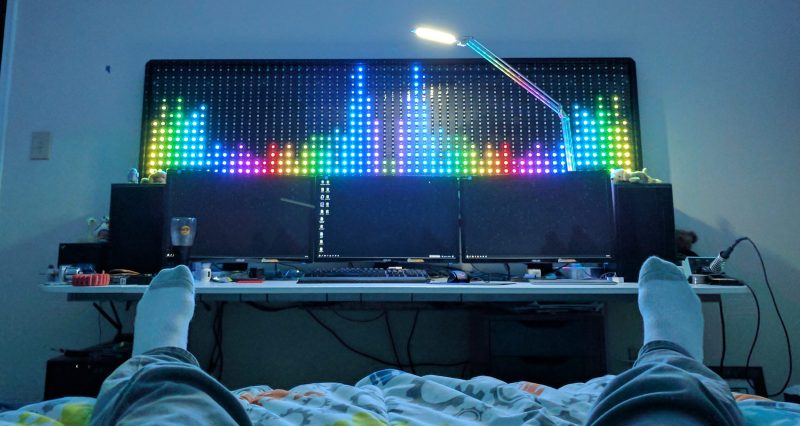
When it comes to wall-mounted ornamentation, get ready to throw out your throw-rugs and swap them for something that will pop so vividly, you’ll want to get your eyes checked. To get our eyes warmed up and popping, [James Best] has concocted a gargantuan 900-RGB-LED music visualizer to ensure that our bedrooms are bright and blinky on demand.
Like any other graduate from that small liberal-arts school in southern California, [James] started prototyping with some good old-fashioned blue tape. Once he had had his grid-spacing established, he set to work on 2-meter-by-0.5-meter wall mounted display from some plywood and lumber. Following some minor adhesive mishaps, James had his grid tacked down with Gaffers tape, and ready for visuals.
Under the hood, a Teensy is leveraging its DMA capabilities to conduct out a bitstream to 900 LEDs. By using the DMA feature and opting for a Teensy over the go-to Arduino, [James] is using the spare CPU cycles to cook out some Fourier-Transformed music samples and display their frequency content.
We’ve covered folks proving the concept of driving oodles of WS2812B LEDs over DMA; it’s great seeing these ideas mature into a fully-featured project that lands on the walll. For more on chatting with WS2812B LEDs over DMA, have a look back into our archive.


A higher tech version of what we used to refer to in the 70s as a color organ.
Thats like saying a pick up truck is just a high tech wheelbarrow
or disco floor
LED wallpaper would be interesting.
The most anoyying part of this project is theres no indication of how he is feeding audio to the teensy. I build stuff like this and I hate wrangling with msgeq7 chips. I’m trying to find easier ways to run the audio sampling.
You can take a look at my Automatic audio switching project as I cover the design for audio frontend – it uses DC coupling with level shifting and an anti-aliasing filter for the ADC. You can ignore the balanced input & MUX on the daughtercard.
It has a spectrum analyzer built-in using an integer FFT.
https://github.com/FPGA-Computer/Automatic-Audio-Switch
Indeed his writeup has impressive details on the physical build doesn’t talk much about the electronics or code.
But it’s very likely he used an ADC pin to sample the audio signal and probably code pretty similar (but fancier animations) to this example:
https://github.com/PaulStoffregen/OctoWS2811/blob/master/examples/SpectrumAnalyzer/SpectrumAnalyzer.ino
If you’re looking for an easier way to sample audio, this is definitely it. (full disclosure – I’m the author of this library, so my opinion may be biased) The Audio library uses DMA and 2 levels of nested priority interrupts to continuously sample the ADC pin at 44.1 kHz, and then to feed that data stream into the FFT analysis which you can then read from the Arduino sketch similar to Serial data. A FFT.available() function tell you when the FFT has produced a new batch of spectral data, and FFT.read() lets you read the frequency bins.
As for getting the analog audio signal into the ADC, while I can’t know exactly how he built it (or whether he used a shield with a dedicated ADC or codec chip), I can tell you this is the recommended circuit for coupling a consume “line-level” audio signal to the ADC pin.
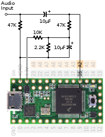
The 10uF capacitor at the top blocks any DC voltage that may be present. The 10K & 2.2K resistors and lower 10uF create a ~0.6V filtered DC voltage, which is added to the signal by the 47K resistor on the right side. The audio library configures the ADC to use the internal stable low-noise 1.2V reference, so the ADC’s range is 0 to 1.2V. Since ordinary line-level signals are about 1 volt peak-to-peak, this circuit maps the audio signal onto 0.1V to 1.1V, using most of the ADC’s range.
The detailed documentation can be found here: (right side documentation panel)
https://www.pjrc.com/teensy/gui/index.html?info=AudioInputAnalog
To finish off this lengthy reply, here’s a link to a 31 page tutorial on how this system works. FFT analysis is covered on pages 24-29 of the PDF. This tutorial was also done as a workshop at Hackday’s first Supercon about 4 years ago.
https://www.pjrc.com/store/audio_tutorial_kit.html
Alysia and I made a 45 minute walkthrough video of the entire tutorial. So if you want to see the FFT part of the tutorial in action (but using a shield with codec chip rather than the ADC pin in that tutorial), just skip forward to 34:56 in the video.
https://www.youtube.com/watch?v=wqt55OAabVs
Or you might watch a while starting at 6:59 for how the design tool and exporting the code into Arduino works. Hopefully it’s pretty easy to see how you could just drag the ADC input onto the canvas rather than the I2S, to generate the code which gets audio input from a built-in ADC pin rather than the extra shield.
>Since ordinary line-level signals are about 1 volt peak-to-peak
If the spectrum display is designed for line level audio input, it had better be able to deal with +/-1.736V input.
FYI: https://en.wikipedia.org/wiki/Line_level
The level shifting divider I have can handle that if you change the 10K resistor into a 12K. With the 10K values, mine is +/-1.65V which won’t happen as the loudness protection would kick in extra attenuation.
Your design have no anti-alias filters, so there would be ghost imaging in the FFT for frequency components exceeding the sampling frequency. It might not be obvious that there are upper harmonics for non-sine waves. :P
My reply is pending or lost… Correct on signal level as it had been a while since I research it.
Consumer audio line level is +/- 1.414V which my circuit handle. Yours will blow up.
It also has proper anti-alias filtering to prevent higher harmonics causing ghosting in the fft output.
Thanks! Will have a look at it!
Just as you guessed I used your ADC audio library and level shifting circuit (I had originally planned to use USB, but had no way to split audio from my computer that way). The circuit was just on a separate board with the level shifted outputs soldered to the teensy. Here’s a picture from a second visualizer i made: (http://subms.com/static/images/led_stair_viz/led_stair_viz_6.jpg) I use a Y cable to split signal between speakers and the visualizer.
I would love to see a build layout and the teensy code as well.
There are numerous projects with various solutions and suggestions posted on this website. Finnding the one that suits your project will require some effort. Not much, but a little at minimum.
Would love to see the build layout and teensy code for this
This was actually the first electronics project I did. built myself a 16 x 64 rgb array just like that and used processing to do the fft. Also mounted it above my computer by its pretty sad actually after only a few days the novelty wears of and it becomes quite annoying. The thing has been gathering dust ever since
my inner kid thinks this is awesome!
Spectrum visualizers can make for fun projects and information to play around with. Ive so far created 3 different ones of varying levels of success.
1) First was just a MSGEQ7 project with a few small led bargraphs.
2) Second was a teensy with FFT sampling the audio signal on it’s ADC driving a set of IN-13 neon bargraphs. It would output the bands as fast PWM signals, RC filter turned that into an analog value that would be fed to transistors that manipulate the current going through the bargraphs
3) Technically just a VU meter, but still happy of it. I had a bunch of Magic eye tubes. So wanted to turn one into just a Vu meter. I amped the audio signal, Used a diode clamper to translate the signal between 0v and negative peak and finally rectified with a diode into a simple RC filter to get a negative peak voltage with a slew rate i could tune.
Recently been experimenting on an Addressable RGB string with the teensy, though rather than go through the hassle of using the DMA and such to keep things from affecting one another i simply use APA102 instead of WS2812. APA102 are Clocked leds which can be driven via simple hardware SPI. So no timing shenanigans and whatnot.
Writing your own low-level library code is indeed a hassle, especially if you try to leverage powerful but complex hardware features.
But why would you bother to write your own WS2812 communication library? Two very mature libraries with DMA already exist (OctoWS2811 and WS2812Serial) and have been used successfully by many thousands of people. These days, a good number of the non-Teensy boards also have DMA-based libs (some more mature & stable than others). Two other non-DMA libs (FastLED and Adafruit_NeoPixel) also work well, but block or interfere with interrupts. FastLED supports using either of the DMA libs as a sort of “driver”, so if you’re wanting the amazing color & rendering features of FastLED, you can have all that, with DMA, simply by changing the driver name in the “addLeds” config.
Many people believe, as you do, that APA102 is technically superior. Adafruit has published praise of APA102 “dotstar”, mainly because so many of the cheaper boards they sold at the time were not capable of DMA and all of their code used simple busy loops. But what they didn’t mention is how APA102 slowly degrades the clock signal as you make the LED strip longer and longer. APA102 “regenerates” the clock with each pixel, but that process is analog. It’s like using a photocopier to make a copy of a copy of a copy. For the slow speeds you can only get from 8 bit AVR, this isn’t much of an issue. But for higher clock speeds, as many people at the time incorrectly believed worked will with APA102 (but could only be done from powerful 32 bit boards), the gradual distortion of the clock on APA102 is indeed a problem. Many, many people discovered they needed to use much lower clocks to get long strips to work reliably.
If you like APA102 or similar 4-wire LED strips, I suppose that’s a personal choice. Just know that nearly all of them “regenerate” the clock signal by an analog process. It’s not like digital copying, the way WS2812 does.
Do you have these for sale?