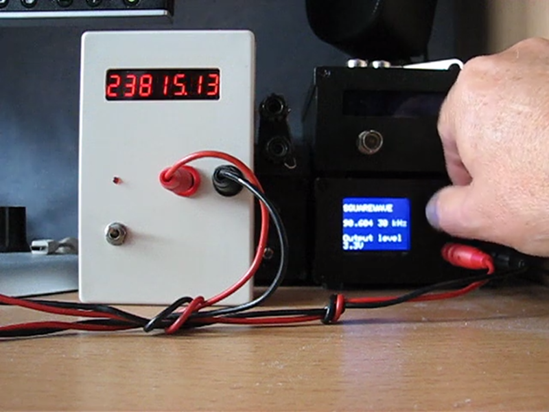
Counting frequency is one of those tasks that seems simple on the face of it, but actually has quite a bit of nuance. There are two obvious methods, of which the first is to count zero crossings for some period. If that period is one second you are done, otherwise it’s a simple enough case of doing the math. That is, if you count for half a second, multiply the result by 2, or if you count for 10 seconds, divide by 10. The other obvious method is to measure the period of a single cycle as accurately as you can. Then there’s this third method.from [WilkoL], which simultaneously counts a known reference clock alongside the frequency to be measured. You can see the result in the video, below.
The first method is easy but the lower the frequency you want to measure, the longer you have to count to get any real resolution. Also, you need the time base to be exact. For the second method, you need to be able to make a highly precise measurement. The reason [WikolL] chose the third method is that it doesn’t require a very precise time base — a moderately accurate reference oscillator will do. The instrument gets good resolution quickly at both high and low frequencies.
The key to making the measurement is a clever way of connecting a D flip flop in such a way that it counts the high frequency reference clock and the lower frequency of interest for a fixed period of time. The fixed period doesn’t have to be very accurate. You wind up with two counts: How many input clocks you saw over the period and how many reference clocks. Since you know the frequency of the reference clock, the rest is simple math.
The real danger to projects like this is you can quickly get obsessed with measuring frequency and time. Of course, we’ve seen plenty of gated counter designs.


With a good enough reference oscillator this method can be amazingly precise and accurate. I used this technique to measure the wavelength of a tunable dye laser, by comparing its frequency with an accurate but fixed-frequency reference laser, after mixing the lasers down to a few dozen MHz and counting the two frequencies directly for a few seconds. It was good to parts per billion, basically limited by the detector and counter bandwidth — precise enough to require correction for the change in dispersion between the two laser wavelengths due to ambient atmospheric pressure, temperature and humidity. A Commodore PET did the number crunching to compute the tunable laser frequency (wavelength). There are better and faster and cheaper ways to measure wavelength now, but this was most accurate way to do it for the cost at the time.
Really, this method is just the same as method #1, isn’t it? After all, it requires you to measure the period of time over which you’re counting the original signal.
Ah, after looking at the pointed-out-page, I see the devil is in the details, regarding exactly when you start and end your measurement.
Better use PICs for this, only they have direct pin-to-counter-clock-input connection. ATs and most other architectures sample their clock pins with system clock, to avoid metastability. Well, now I am having second thoughts on “Better…”, but anyway, have that in mind when designing microcontroller based frequency meters: check the signal paths in your datasheets.
Well, the ATmega328 has timer2 that does live in a separate clock domain and can be run asynchronously from the rest of the system. Its limited resolution of 8 bits make it a bit cumbersome to use.
The LPC812/LPC824 from NXP have a state configurable timer that is also capable of running in its own clock domain. Those timers are pretty powerful statemachines+counter blocks that can do all kinds of nifty things.
Be aware that writing peripheral registers in different clock domains have a few gotchas, I remember that the atmega timer2 has a chapter on that. Not sure on the LPC as they are often setup at different clock domains. Clocking is a good deal more complex on arm processors.
The PIC165x app note AN592 “Frequency Counter Using PIC16C5X”. They are using it for a 50MHz frequency counter with a single resistor.
It has a 8-bit timer, but they cheated and use the 8-bit prescaler for 16-bit. They count the extra clocks needed for the prescaler to overflow to extract the value there. The actual limits here is your imagination.
link: ww1.microchip.com/downloads/en/AppNotes/00592d.pdf
Pretty much all of the TI (MSP430/MSP532, etc) processors have direct clocking, as well (latch-and-sample can be enabled or disabled). In fact, I have never worked on an architecture where direct clocking wasn’t generally possible, though I have used libraries that only allow synchronous sampling, and it would not surprise me if there were architectures with sampled-only.
Measuring period is using only 1 sample vs multiple samples for counting pulses. So if the clock you are measuring have a lot of jitters, you might see the frequency changes more between readings.
Key search terms: “reciprocal counter” and “statistical counter”.