Wall-Mounted Ground Station Tames Unruly SatNOGS Node

For many of us, ad hoc projects end up having a certain permanence to them. Think of the number of Raspberry Pis and RTL-SDRs that are just dangling from a USB cable under a desk or stuffed behind a monitor, quietly going about their business. If it ain’t broke, don’t fix it.

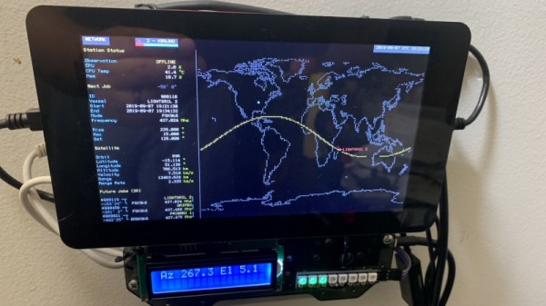
Some projects, though, just end up accreting past the acceptable point. This wall-mounted SatNOGS ground station is a great example of what happens when something needs to be done about the mess. The pile of stuff that [cshields] had cobbled together over time for his ground station needed tidying, so he laid hands on a new Pi 4 and a cool enclosure/breadboard called a Stegoboard. This is just a piece of acrylic with a variety of holes laid out to match every imaginable PC board, hard drive, PC motherboard, Arduino, and just about anything out there that needs mounting. To contain the mess, he mounted the Pi and a 7″ touchscreen to the Stegoboard, along with an RTL-SDR and an Arduino to control his antenna rotator. The ground station wiring is still a little rough, but worlds better than what it was, and now that it’s mounted on the wall it’ll be much easier to use.

For those not familiar with SatNOGS, check out our article back from when the Satellite Network of Ground Stations won the 2014 Hackaday Prize. In the half-decade since then, SatNOGS has only grown, with a huge following of dedicated enthusiasts pointing their antennas at the sky. We know how to pick ’em, and we’ll be selecting the 2019 Hackaday Prize winner very soon.

Thanks to [elkos] for the tip.

Frequency Counting A Different Way

Counting frequency is one of those tasks that seems simple on the face of it, but actually has quite a bit of nuance. There are two obvious methods, of which the first is to count zero crossings for some period. If that period is one second you are done, otherwise it’s a simple enough case of doing the math. That is, if you count for half a second, multiply the result by 2, or if you count for 10 seconds, divide by 10. The other obvious method is to measure the period of a single cycle as accurately as you can. Then there’s this third method.from [WilkoL], which simultaneously counts a known reference clock alongside the frequency to be measured.  You can see the result in the video, below.

The first method is easy but the lower the frequency you want to measure, the longer you have to count to get any real resolution. Also, you need the time base to be exact. For the second method, you need to be able to make a highly precise measurement. The reason [WikolL] chose the third method is that it doesn’t require a very precise time base — a moderately accurate reference oscillator will do. The instrument gets good resolution quickly at both high and low frequencies.  Continue reading “Frequency Counting A Different Way”

These Tips Make Assembling A Few Hundred PCBs Easier

There are a few common lessons that get repeated by anyone who takes on the task of assembling a few hundred PCBs, but there are also unique insights to be had. [DominoTree] shared his takeaways after making a couple hundred electronic badges for DEFCON 26 (that’s the one before the one that just wrapped up, if anyone’s keeping track.) [DominoTree] assembled over 200 Telephreak badges and by the end of it he had quite a list of improvements he wished he had made during the design phase.

Some tips are clearly sensible, such as adding proper debug and programming interfaces, or baking an efficient test cycle into the firmware. Others are not quite so obvious, for example “add a few holes to your board.” Holes can be useful in unexpected ways and cost essentially zero. Even if the board isn’t going to be mounted to anything, a few holes can provide a way to attach jigs or other hardware like test fixtures.

[DominoTree] ended up having to attach multiple jumper wires to reprogram boards after assembly, and assures us that “doing this a bunch of times really sucked.”
Other advice is more generic but no less important, as with “eliminate as many steps as possible.” Almost anything adds up to a significant chunk of time when repeated hundreds of times. To the basement hacker, something such as pre-cut and pre-tinned wires might seem like a shameful indulgence. But cutting, stripping, tinning, then hand-soldering a wire adds up to significant time and effort by iteration number four hundred (that’s two power wires per badge) even if one isn’t staring down a looming deadline.

[DominoTree] also followed up with additional advice on making assembly easier. Our own [Brian Benchoff] has also shared his observations on the experience of developing and assembling a large number of Hackaday Superconference badges, including what it took to keep things moving along when inevitable problems surfaced.

You don’t need to be making batches of hundreds for these lessons to pay off, so keep them in mind and practice them on your next project.

Particle Mesh Powers The Internet Of Fans

With the winter months not far off, [Ben Brooks] was looking for a way to help circulate the heat from his wood-burning fireplace throughout his home. Rather than go with a commercial solution, he decided to come up with his own automated air circulation system powered by the mesh networking capabilities of one of his favorite pieces of tech, the Particle Photon.

Particle Xeon remote sensor

The idea here is pretty simple: use a remote temperature sensor to tell a fan located behind the fireplace when it’s time to kick on and start sharing some of that warmth with the rest of the house. But as usual, it ended up being a bit trickier than anticipated. For one, when [Ben] took a close look at the Vornado 660 fan he planned on using, he realized that its speed controller was “smart” enough that simply putting a relay on the AC line wouldn’t allow him to turn it on and off.

So he had to do some reverse engineering to figure out how the Sonix SN8P2501B microcontroller on the board was controlling the fan, and then wire the Photon directly to the pins on the chip that corresponded with the various physical controls. This allows the Photon to not only “push” the buttons to trigger the different speeds, but also read the controls to see if a human is trying to override the current setting.

For the remote side [Ben] is using a Particle Xenon, which is specifically designed for Internet of Things endpoints and sensor applications. Combined with a TMP36 temperature sensor and 3.7 V 500 mAh battery, this allowed him to easily put together a wireless remote thermometer that will publish the current temperature to the Photon’s mesh network at regular intervals.

This isn’t the first time we’ve seen the Particle Photon used to augment an unassuming piece of hardware. We’ve previously seen one get grafted into a coffee maker, and if you can believe it, somebody even stuck one inside an umbrella to create a mobile weather station.

A 4G Rover And The Benefits Of A Shakedown Mission

Many moons ago, in the shadowy darkness of the 1990s, a young Lewin visited his elder cousin. An adept AMOS programmer, he had managed to get his Amiga 500 to control an RC car, with little more than a large pile of relays and guile. Everything worked well, but there was just one problem — once the car left the room, there was no way to see what was going on.

Why don’t you put a camera on it? Then you can drive it anywhere!

Lewin

This would go on to inspire the TKIRV project approximately 20 years later. The goal of the project is to build a rover outfitted with a camera, which is controllable over cellular data networks from anywhere on Earth. For its upcoming major expedition, the vehicle is to receive solar panels to enable it to remain operable in distant lands for extended periods without having to return to base to recharge.

The project continues to inch towards this goal, but as the rover nears completion, the temptation to take it out for a spin grew ever greater. What initially began as an exciting jaunt actually netted plenty of useful knowledge for the rover’s further development.

Continue reading “A 4G Rover And The Benefits Of A Shakedown Mission”

Modified Tombstone Welder Contains A Host Of Hacks

State-of-the-art welding machines aren’t cheap, and for good reason: pushing around that much current in a controlled way and doing it over an entire workday takes some heavy-duty parts. There are bargains to be found, though, especially in the most basic of machines: AC stick welders. The familiar and aptly named “tombstone” welders can do the business, and they’re a great tool to learn how to lay a bead.

Tombstones are not without their drawbacks, though, and while others might buy a different welder when bumping up against those limits, [Greg Hildstrom] decided to hack his AC stick welder into an AC/DC welder with TIG. He details the panoply of mods he made to the welder, from a new 50 A cordset made from three extension cords where all three 12 gauge wires in each cord are connected together to make much larger effective conductors, to adding rectifiers and a choke made from the frame of a microwave oven transformer to produce DC output at the full 225 A rating. By the end of the project the tombstone was chock full of hacks, including a homemade foot pedal for voltage control, new industry-standard connectors for everything, and with the help of a vintage Lincoln “Hi-Freq” controller, support for TIG, or tungsten inert gas welding. His blog post shows some of the many test beads he’s put down with the machine, and the video playlist linked below shows highlights of the build.

This isn’t [Greg]’s first foray into the world of hot metal. A few years back we covered his electric arc furnace build, powered by another, more capable welder.

Continue reading “Modified Tombstone Welder Contains A Host Of Hacks”

Watching The Watchers: The State Of Space Surveillance

By now you’ve almost certainly heard about the recent release of a high-resolution satellite image showing the aftermath of Iran’s failed attempt to launch their Safir liquid fuel rocket. The geopolitical ramifications of Iran developing this type of ballistic missile technology is certainly a newsworthy story in its own right, but in this case, there’s been far more interest in how the picture was taken. Given known variables such as the time and date of the incident and the location of the launch pad, analysts have determined it was likely taken by a classified American KH-11 satellite.

The image is certainly striking, showing a level of detail that far exceeds what’s available through any of the space observation services we as civilians have access to. Estimated to have been taken from a distance of approximately 382 km, the image appears to have a resolution of at least ten centimeters per pixel. Given that the orbit of the satellite in question dips as low as 270 km on its closest approach to the Earth’s surface, it’s likely that the maximum resolution is even higher.

Of course, there are many aspects of the KH-11 satellites that remain highly classified, especially in regards to the latest hardware revisions. But their existence and general design has been common knowledge for decades. Images taken from earlier generation KH-11 satellites were leaked or otherwise released in the 1980s and 1990s, and while the Iranian image is certainly of a higher fidelity, this is not wholly surprising given the intervening decades.

What we know far less about are the orbital surveillance assets that supersede the KH-11. The satellite that took this image, known by its designation USA 224, has been in orbit since 2011. The National Reconnaissance Office (NRO) has launched a number of newer spacecraft since then, with several more slated to be lifted into orbit between now and 2021.

So let’s take a closer look at the KH-11 series of reconnaissance satellites, and compare that to what we can piece together about the next generation or orbital espionage technology that’s already circling overhead might be capable of.

Continue reading “Watching The Watchers: The State Of Space Surveillance”