Pong is a classic from the very dawn of the video game era. Recreating it remains a popular exercise for those new to coding. However, its simple logic makes this game particularly suited to an all-hardware build; something which [Glen] tackles with aplomb.
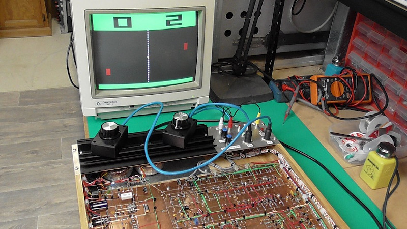
Not content to take the easy way out, [Glen] went for a particularly hardcore method of construction. The game uses absolutely zero integrated circuits in its construction. Instead, it relies upon the services of 431 bipolar transistors, 6 JFETs and 826 diodes. Everything is laced together on protoboard, connected with a neatly organised nest of colored wires. Schematics are available for the curious.
It’s a full featured build, too. Video output is in color, scores are displayed at the top of the screen, and there’s even stereo panning for the sound effects. It just goes to show what some humble components can do when put to work in the right way. We’ve seen some of [Glen]’s work before too, for example in this op-amp bouncing ball device. Video after the break.


Considering the original was an all hardware build I would say yes pong is well suited for an all hardware build
Except the original was incorporated ttl integrated circuits, was black and white, and had only single channel sound.
I know that, its not a dig at the progect, its just yet another hackaday wtf logic loop “we know its good first software excercise but its simple logic lends it to hardware” I was trying to say no shit clueless author, the original was all hardware as well quit padding your articles with nonsense
You know when you posted your diatribe – did you see this just underneath it:
“Please be kind and respectful to help make the comments section excellent. (Comment Policy[URL])”?
I think I would be universally agreed with when I say that abuse is not welcome at HAD…
Whow! A crazy project, so neatly documented. I am mostly impressed by the very high standard in documentation. I wish any of the projects I had to do with at work would have been documented like this. No bla-bla nonsense, but all the important information is there. Neat diagrams show all the timings and the basic design idea clearly, mostly without words.
And the understatement of the month in the introduction: “… for those with a couple of hours to spare who therefore might wish to build their own”. “A couple hundred hours” sounds more realistic to me…
Thank you for this inspirational piece of art!
I sense a soldering kit is in the works…
Just Checked RS – 500 of BC550C for £70.80, might have to treat myself to a Christmas Box of them!!!!
wow… very nice.
Well done!
Impressive build
I believe Ralph Baer made the first Pong Type game out of Discrete transistors https://en.wikipedia.org/wiki/Magnavox_Odyssey
Matt
Amazing, unbelievable work. I love all those discrete emitter-coupled flip-flops and monostable multivibrators. Love the diode OR gates. Really well-thought-out design and a well-labelled, understandable schematic.
That said, I would NEVER attempt a project like this! From one engineer to another, my hat’s off to Glen!
I can’t imagine of doing it from scratch.
How is this designed initially? Is it made from a vhdl/verilog and finally concerted to discrete by making flip-flop, mix, SR blocks to discrete equivalent or how ? I am still confused how someone designed it :)
I believe the arcade version of pong has it’s schematics available, so that might have been the starting point.
But I am wondering how it is designed. Will it be designed at first on HDL and tested on an FPGA and then used the result to implement the blocks using transistors ? Because am not able to imagine where is the start to make such a big circuitry from scratch.
The thing that impresses me the most is the very clear structure (and documentation) of the whole design. The function blocks are so neatly defined that the remaining design process looks more like a routine job.
The core logic is not very complex. A 5 bit counter for horizontal, 9 bit for vertical and a couple of OR gates to generate to strobe pulses to trigger events.
The point counters are just 5 bit counters with a 7-segment decoder (OR gates again).
The most complex part is the analog. There are some level shifters and buffers for the video signal, but most of it is made of OpAmp-like structures.
All these blocks are simple enough for a real pen-and-paper design, no need for computer help here.
All the gates are build using classic DTL logic – lots of diodes, some pullup resistors and a buffer transistor at the output. The OpAmps are classic designs as well and every building block (flipflop for counter, OR gate, OpAmp) can be tested individually. The rest is a matter of copy and paste.
Nothing overly complicated here. But coming up with that clear structure – that’s the key.
Complete madness!
I love it!
I love it. Good explanation, good schematic, and an absolutely beautifully laid out board.
Totally brilliant, totally inspiring! Thanks
IC, uhhh i see its portable too!
I came here from the link in https://hackaday.com/2022/08/08/was-there-a-programmable-pong-chip/
Bloody good job, thanks for sharing. Nice to see an old Commodore monitor still in service too!