If you owned a classic Commodore home computer you might not have known it at the time, but it would have contained a versatile integrated circuit called the MOS6526. This so-called CIA chip, for Complex Interface Adaptor, contained parallel and serial ports, timers, and a time-of-day counter. Like so many similar pieces of classic silicon it’s long out of production, so [Daniel Molina] decided to replicate a modern version of it on a PCB using 74HGT CMOS logic.
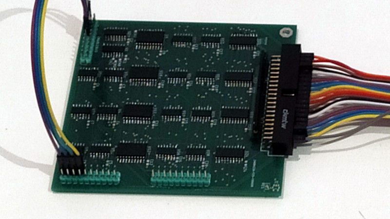
The result will be a stack of boards board that appear to be about the size of a 3.5″ floppy disk covered in surface-mount 74 chips, and connected to the CIA socket of the Commodore by a ribbon cable. The base board is the only one completed so far and contains the data direction registers and parallel ports, but the succeding boards will each carry one of the chip’s other functions.
It seems rather odd to use so much silicon to recreate a single chip, but the point is not of course to provide a practical CIA replacement. Instead it’s instructive, it shows us how these interfaces work as well as just how much circuitry is crammed into the chip. It’s no surprise that it’s inspired by the C74 Project, a TTL 6502 processor that we featured last year.


I love those exploded views. In our own minimalistic TTL project we frequently get suggestions to throw in such interface devices. But doing so goes completely against the grain of the Gigatron project. Our motto is: “as long as you can do it in software, you don’t need extra hardware for it”. As this CIA project shows, interface chips are just as complex beasts as are video and sound chips. We have none of that and still we’re reading from memory cards while at the same time we’re displaying 64 color video and playing 4-channel sound. All time-multiplexed on a simplistic 7400-based CPU with half the logic gates of a 6502. From a purist point of view I still regret the 8-bit shift-register that’s doing the keyboard input, and people ask for UARTs and video chips… Ofcourse the project is a curiosity and only half serious, because the software effort to make it all tick is considerable and system performance is barely acceptable. But every TTL-based project is a curiosity, and should pick it’s own constraints to play with. [Ok, end of rant, back to FAT32 handling.]
There will be a bit if of wasted silicon as the “chip” configuration is static in the C64. i.e. some of the port bits are always used as inputs and some are always outputs. i.e. individual configuration register bits in DFF and the extra logic for the port direction not used.
The layout isn’t a reflection on complexity. It is around at most 30-40% area which could have be squeeze by a factor of 2 by someone more skillful.
Hi! Not so skilled creator here! (No offense, you’re actually right)
While it is true than some ports are static in the C64 (ie, PA0 and PA1 on CIA#2, used for VA14 and VA15), the MOS6526 allows for any configuration, as the CIAs are generic ICs which could be used for wherever the designer had on his mind. The 6526 can also be found in other hardware, such as the 1571 disk drive, so allowing for all possible combinations was part of my idea.
Regarding my skills, I’m an absolute beginner in almost every area I’m touching. This is my first SMD board, and I’ve only practice a bit before with SMD parts. Before this, I’ve only made ONE board with DIP components, to assemble an EPROM programmer, just an exercise, so I’m learning as I go. It’s true this board is very low density packed, and as I gain confidence and expertise, it’s getting better. B1 and B2 are already more densely packed, and there’s still room for improvement.
So…
“There aren’t spooks in a Commodaore C64?
Maybe building a CPLD version would be more beneficial both for the creator and the community.
Could probably do it on a PIC… Any artist chooses the medium they are most comfortable and appropriate for the work they wish to create. 74xx chips are the basic logic gates, use to recreate the function. The goal doesn’t seem to be repair or replacement, of a discontinued chip, but to just see if it can be done, how it could be done, and if it would actually work. Mostly a personal challenge, rather than an actual need for the chip.
I remember seeing a whole C64 on a single chip some place. There are emulators online, and for download. if your want or need to use a C64. They were amazing computers at the time, and for the price. They pack a lot of function, into a small space, for a reasonable price. No SMD parts either!
The point—–> .
You————>
That’s an awesome project! Very well done. It’s a pleasure to walk through the old chips and see just how much they are doing for you! And it doesn’t matter if you do your project using FPGA’s, micro controllers, LSI, MSI, SSI, Transistors or even Tubes! It’s the fact that you did it that really counts! And just say Bah, when you get a negative comment from a critic! I wish people were more “skillful” at writing polite positive comments!
What a beautiful object. And a lot of hard work to make it work properly. Nicely done.
What would be more beneficial about a CPLD version?
Hi! For the community, same as projects like SwinSid or FPGASid. I understand the need of a drop-in, viable replacement for obsolete ICs, as many people want to keep this old computers running in its original form. There will be a point, as more and more old chips die, when getting an original CIA (Or SID, or VICII) will be difficult and expensive.
For me… well… my main goals are to learn, and to have some fun along the way. Discrete logic seemed more fun than CPLD :)
Well done and something to be proud of.
There is a problem with implementing the CIA using TTLs. The CIA is an NMOS chip, so the outputs use NMOS drivers. Those have different characteristics than TTL output drivers, especially if you use HCT. You can, for example, have two NMOS outputs work against each other (one HIGH and one LOW) without causing damage. So some of the programming hacks used in the C64 will not work with this replacement.
Hi! You’re absolutely right. The ‘analog’ aspects of this project are the one that are causing me more troubles, and the PortA and PortB outputs have been quite annoying. B0 is already an “old” design. I did it and ordered the PCBs almost half a year ago, and I’ve noticed plenty of needed changes since them.
I’ve managed to get some hi-res pics of the original chip die, and I’ve even found that each port has different output/input characteristics between them, so there’s a lot to do.