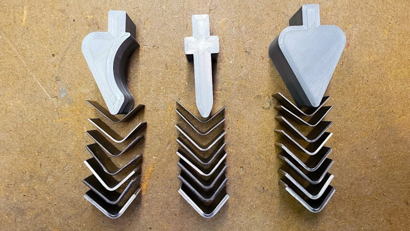
Press brakes are a workshop staple when working with sheet metal. They’re ideal for executing accurate and repeatable bends over and over again. Typically, they’re fitted with steel tooling that can hold up to thousands of press cycles. However, such tooling is expensive, and time consuming to produce. [Anthony] recently had a job come through the shop that required a unique internal radius. Rather than rush out and buy tooling, he decided to 3D print his own instead!
The press brake tools were printed on a standard Prusa i3, using regular PLA filament. There’s nothing particularly special in the process, with the prints using 12 perimeters and 20% infill. Despite being made of plastic, the tools held up surprisingly well. In testing, the parts were able to bend up to 3.4 mm steel, undergoing several cycles without major visible wear. [Anthony] also experimented with gooseneck parts, which, while less robust, make it easy to accommodate more complex sheet metal parts.
3D printing is a great way to produce custom press tooling, and can be done far more cheaply and quickly than producing traditional steel tooling. While it’s unlikely to be useful for long production runs, for short runs that need custom geometry, it’s a handy technique. We’ve even seen 3D printed punch-and-die sets, too. Video after the break.


I don’t have a brake, but dies printed to fit the jaws of my bench vise actually work really well for stuff less than the 5″ width or 2″ depth of the jaws, as long as you don’t have a lot of parts to do.
Indeed.
I started with the same and now I use a harbor freight 20 ton shop press. Gives you the ability to feed long pieces of work through it. 😉
I haven’t tried 3D printing dies for my brake, but I do often print fixtures for making comparative measurements in the shop.
I often find myself drilling holes in long sections of pipe that need to be on the same plane and so far the most repeatable method has been to make a pair of clamps with a bubble vial in them. Basically I clamp the pipe in the mill vise and put on of the levels on each end…as long as they are both level, I can move up and down the pipe as needed and know that all the holes are in the same plane within a reasonable tolerance. I normally leave one as a “reference” and move the other along the pipe as needed.
I’m going to have to steal this -thanks!
Paging Professor Parabellum….
You thinking 3d printed tooling for a stamped gun? I keep thinking about replacing the stamped steel with prepreg carbon fiber.
Yes a very cool clever idea. I am surprised they hold up as well as they do. We used to laser cut the punch profile, out of .125 stock, then cut, stack and tack weld, enough blanks to make the width of formed part. If it was a short run we would use it for the run. Other wise as a sample for a machined punch, after testing.
Thanks for the info.
These guys do quality 3D press brake tooling and any other 3D printing in polymer and metal, check them out if you need something printed.
https://www.wilsontool.com/en-US/Products/Additive