What’s the weirdest computer you can think of? This one’s weirder.
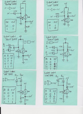
[Dr. Cockroach] figured out a way to create an inverting NOT gate from just one LED and two resistors (one being a photo-resistor). The Dr. has since built AND, NAND, OR, NOR, XOR and XNOR gates, as well as a buffer, incorporating light into every logic gate.
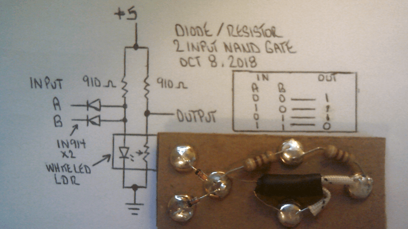
Traditional inverters – NOT gates – are already made with diodes (typically not light-emitting), resistors (typically not light-dependent), and bipolar transistors. The challenge was to reduce the number of transistors. The schematic from the very first test shows the slight modifications [Dr. Cockroach] made to incorporate light into the logic gate using a 910 Ohm, output LED, and an LED and LDR in parallel.
The output is initially 4.5V for logic 1 and 1.5V for logic 0. Adding two 1N914 diodes and an AND gate ahead of the inverter create a two-input NAND gate. With the two diodes reversed and a 910 Ohm resistor removed, a NOR gate is created.
The next step was to build a S-R latch using the NAND gates and inverters, which holds some basic memory. From there, with some size reductions, a Master-Slave J-K Flip Flop, similarly using NAND gates and inverters, can be built. The current state of the project is a working sequencer and counter. You can even see a smooth sine wave propagating through the LED chaser, which is typically built with ICs or transistors but in this case is built simply with LEDs, LDRs, resistors, and capacitors.
The upcoming plan is to use the gates to build a processor that only uses diodes, resistors, and capacitors. While it’s probably not going to be nearly as fast as any processors we have today, it should be interesting (and educational!) to be able to visually track the flow of data from one logic gate over to the next.


GG !
Yay for Dr. Cockroach! This is a very interesting concept and he’s done a lot of progress over the time he’s working on this, I like showing his vids whenever the topic of non-standard logic comes up =)
Thanks for the write up. There is so much I want to do with Light Logic and see how far I can take it and this winter will be interesting.
Entertaining idea! You must have a cheap source of LED-photoresistor couplers; they are not cheap.
Did you consider using the more common LED-phototransistor optocouplers? It’s pretty easy to find ones with a CTR > 100 (i.e. gain so you’d have a fan-out > 1). They would be an order of magnitude faster, too.
Semi-local friend of The Good Doc here… he’s actually making the optocouplers himself, individually, by hand…
As for involving transistors, kind of his whole point is to demonstrate what can be done WITHOUT them. He’s actually told me, earlier today, that he intends to get some old-fashioned Grain-Of-Wheat bulbs if he can, and see if he can go /completely/ semiconductorless and get away with it. TBH I’m quite intrigued.
Worth noting, photoresistors /are/ quite slow, and they are incredibly imprecise… yes, phototransistors would be faster and in some ways better… but, again, his whole point is to demonstrate that they actually are unnecessary in a sense. Sort of the spirit of Light Logic is, hey, what if we could make all this modern stuff we have (or something kind of like it), at least up to I’d say mid-1960s-era tech, computers included — but with something more advanced than relays and vacuum tubes that also somehow wasn’t semiconductor-based…? Kind of a Fallout-but-before-the-Vaults-ish-sorta-style alternate-history version of how things wound up, if you get my drift. I think it’s incredibly cool.
”old-fashioned Grain-Of-Wheat bulbs”
Would that be a resistor-resistor logic?
RRL, I like that :-)
If he wants to go completely semiconductorless, then he has to ditch the diodes and CdS cells as well.
The only remaining option then is NTC/PTC resistors
Ditching the Leds is not a problem but the CdS? Well, Cds is technically semiconducting, but it is at least bidirectional and not silicon but thanks for the input :-)
I hope you know, that a photoresistor is a semiconductor device.
I’ll have to research that… I’ve never heard it categorized as such.
Update a few minutes later… Wikipedia indeed categorizes cadmium sulfide as a semiconductor. As previously indicated, that’s a new one to me — but I cannot and will not argue with Wiki.
You really do learn something new — at least one thing — every day, I suppose… ;)
> old-fashioned Grain-Of-Wheat bulbs
Incandescent bulbs can be used as photo-detectors as well as light sources – maybe they could be used to replace the LDRs as well.
How does that work? I’ve never heard it before.
Forest Mims has shown that LEDs can be light receivers as well as emitters, an example he showed long ago was sending messages back and forth along fibre optics.
Michael
Believe it or not but I get my Leds from holiday light strings that are sold at a local thrift store so that yields 100 Leds for a dollar or two and I bulk bought 300 CdS Photo Resistors. Those two components are hot glued to each other then light isolated from stray sources using either shrink tubing or black finger nail color. Doing without any transistors as I want to see just what a DRL gate can do. Not fast but sure is fun.
“from scratch”, “one LED and two resistors (one being a photo-resistor)” yeah right..
Semi-local friend of Dr Cockroach here… I’ve seen his work in person, and, yes, all this is hand-built, mostly from LED Christmas lights and CdS cells out of old nightlights and the like… he’s an incredibly clever scavenger. You really shoud head on over to the [dot]IO side and take a look before you scoff (more) — while it really does sound rather improbable, it does indeed work as advertised.
Having said that… the most important aspect of any science experiment (electronic endeavors included) is repeatability. If you think he’s faking it, take a look at the documentation, and make your own… considering how thorough he’s being with the paperwork, it should be a relatively trivial task indeed… and I think that you’ll be surprised and intrigued by the results.
Give me a break. It isn’t fair to call this cheating. Can a baker not call his cake made from scratch if he picked out and mixed all his ingredients by hand and baked his cake, only to use Duncan Hines frosting? The idea is that this is a novel idea and it’s using commodity parts to build an integrated circuit without most of the complex micro silicon wafers required. He even skipped the transistors.
Exactly :-)
I do not condemn the work reported by the article, which is interesting, but the title chosen by hackaday.
If we say “from scratch” for everything, the words lose their meaning
“If you wish to make apple pie from scratch, you must first create the universe”?
ACHTUNG!
ALLES TURISTEN UND NONTEKNISCHEN LOOKENSPEEPERS!
DAS KOMPUTERMASCHINE IST NICHT FÜR DER GEFINGERPOKEN UND MITTENGRABEN! ODERWISE IST EASY TO SCHNAPPEN DER SPRINGENWERK, BLOWENFUSEN UND POPPENCORKEN MIT SPITZENSPARKEN.
IST NICHT FÜR GEWERKEN BEI DUMMKOPFEN. DER RUBBERNECKEN SIGHTSEEREN KEEPEN DAS COTTONPICKEN HÄNDER IN DAS POCKETS MUSS.
ZO RELAXEN UND WATSCHEN DER BLINKENLICHTEN.
Ah ja, da hast du recht
hihi, großartig! :D
Uhm… gesundheit?
I’m sorry, sir, but I really don’t know any German, and Google Translate does not understand you completely. Also, please turn off your capslock — on the Internet, all caps is equivalent to yelling in someone’s ear and is very rude.
I hope you’re joking, because that’s the standard comedy sign in faux-German to put up on technical equipment which has rows of blinking lights.
They are otherwise known as “das blinkenlights”.
http://www.google.com/search?q=das+blinkenlights+warning
Yes, in 1972 visiting a university open house I saw such a message, maybe not as long, on a piece of equipment. It was obvious then, when I was 12.
ARGH!
Maybe I need a bit more sleep ;) I’m really not sure how I missed that one.
It’s a joke. Also, people stopped calling caps yelling like years ago. In addition, yelling is a physical action requiring vocal chords and physical presence for you to hear me (and it’s also the sign of an idiot losing an argument.)
“Also, people stopped calling caps yelling like years ago. ”
I thought “years ago” it was _all_ caps, on a TTY.
B^)
Fantastic to show inverting logic without transistors. And with that, the entire logic gate family. Diode logic isn’t supposed to be universal. But now it is.
Yeah, except a CdS cell is effectively a “transistor” when you set it up like this. It works like a FET that’s excited by light instead of an electric charge.
The FET was actually invented in the 1920’s but they couldn’t manufacture it, and the transistor invented by Shockley et. al in the 1950’s happened due to them trying to implement the FET, and in trying to figure out why it didn’t work they stumbled upon the BJT.
Oh yes I have read about the 1920’s circuit and fount it way ahead of its time and very interesting.
I love how HaD runs an scare article on the dangers of lead, but then praises a design incorporating Cadmium as a key component. HaD has truly joined the rest of the media.
Well, when you consider that here in the states, CdS photocells are built into off the shelf night lights to be used in children’s rooms that CdS is already out there but all these cells are sealed. I know better than to work with raw CdS materials :-)
It isn’t raw cadmium. It’s sealed in epoxy. Also, it’s coated in shrink/painted black. It’s pretty safe and it’s sealed up tight. You also confuse the level of cadmium in a CdS cell with the amount required to poison a human being.
No pizza boxes or paper clips?
Not on this project yet but check out my other build from last year and some boxes were harmed ;-)
https://hackaday.io/project/19048-the-cardboard-computer-io-is-my-name
Very nice and interesting project. It reminds me of similar projects that built logic gates with neon lamps and fotoresistors (LDRs) e.g. https://hackaday.com/2014/09/29/a-nixie-clock-with-neon-bulb-logic/
I think there was at least another one here in HAD also (I can’t find it now) with a reference to a “historic” design (early computer circuits with logic gates built witn neons and LDRs).
Best regards,
A/P Daniel F. Larrosa
An extract from that article:
“This clock was inspired by a few circuits found in a 1967 book Electronic Counting Circuits by J.B. Dance.
The theory of these circuits rely on the different voltages required to light a neon lamp (the striking voltage) versus the voltage required to stay lit (the maintaining voltage).
If you’re exceptionally clever with some diodes and resistors, you can create a counting circuit with these lamps, and since it’s pretty easy to get the mains frequency, a neon logic clock starts looking like a relatively easy project.”
Thank you for this. This is what I call truly a hack. It’s quite a novel idea. If I ever need a quick and dirty logic gate, I know how to cook one up from my parts bin now!
Yes and thanks, A junk box transistor is many steps better than the Led/CdS combo but I like to step backwards and discover what can be done with alternate materials :-)
Nice project Dr. Cockroach! Have you considered the possibility of making cuprous oxide diodes from scratch, or exploring the possibility of using them, or the LEDs as photodiodes?
Oh yes, A friend has talked to me about cuprous oxide and its properties but I just have not done any experiments as of yet. I have not had good luck in trying to use a Led as a photo detector. Another friend had sent me some PIN Diodes to work with in radiation detectors so I might work with them at a later date :-)