Out in the countryside, having a cow or to two wouldn’t be a big deal. You can have a cattle shed full of them, and no one will bat an eyelid. But what if you’re living in the big city and have no need of pet dogs or cats, but a pet cow. It wouldn’t be easy getting it to ride in the elevator, and you’d have a high chance of being very, very unpopular in the neighbourhood. [Dane & Nicole], aka [8 Bits and a Byte] were undaunted though, and built the Moomba – the Cow Roomba to keep them company in their small city apartment.
The main platform is built from a few pieces of lumber and since it needs to look like a Roomba, cut in a circular shape. Locomotion comes from two DC geared motors, and a third swivel free wheel, all attached directly to the wooden frame. The motors get their 12V juice from eight “AA” batteries. The free range bovine also needs some smarts to allow it to roam at will. For this, it uses a Raspberry Pi powered by a power bank. The Pi drives a 2-channel relay board which controls the voltage applied to the two motors. Unfortunately, this prevents the Moomba from backing out if it gets stuck at a dead end. For anyone else trying to build this it should be easy enough to fix with an electronic speed controller or even by adding a second 2-channel relay board which can reverse the voltage applied to the motors. The Moomba needs to “Moo” when it feels like, so the Raspberry Pi streams a prerecorded mp3 audio clip to a pair of USB speakers.
If you see the video after the break, you’ll notice that making the Moomba sentient is a simple matter of doing “ctrl+C” and “ctrl+V” and you’re good to go. The python code is straight forward, doing one of four actions – move forward, turn left, turn right or play audio. The code picks a random number from 0 to 3, and then performs the action associated with that number. Finally, as an added bonus, the Moomba gets a lush carpet of artificial green grass and it’s free to roam the range.
At first sight, many may quip “where’s the hack” ? But simple, easy to execute projects like these are ideal for getting younglings started down the path to hacking, with adult supervision. The final result may appear frivolous, but it’ll excite young minds as they learn from watching.
IoT devices rarely ever just do what they’re advertised. They’ll almost always take up more space than they need to – on top of that, their processor and memory alone should be enough to run a multitude of other tasks while not necessarily compromising the task they were built to do.
That’s partially the motivation for rooting any device, but for Xiaomi devices, it’s a bit more fun – that is to say, it’s a little bit harder when you’re reverse engineering its firmware from scratch.
Similar to his other DEF CON 26 talk on modifying ARM Cortex-M firmware, [Dennis Giese] returns with a walkthrough of how to reverse-engineer Xiaomi IoT devices. He starts off talking about the Xiaomi ecosystem and the drawbacks of reusing firmware across all the different devices connected to the same cloud network before jumping into the walkthrough for accessing the devices.
Nothing spoils your mood quite like your windscreen wipers not feeling it when the beat drops. Every major car manufacturer is focused on trying to build the electric self driving vehicle for the masses, yet ignoring this very real problem. Well [Ian Charnas] is taking charge, and has successfully slaved his car’s wipers to beat of its stereo.
Starting with the basics, [Ian] first needed to control the speed of the wiper motor. This was done using a custom power supply adapted from another project. The brain of the system is a Raspberry Pi 3B+ which runs a phase locked loop algorithm to sync the music and the motor. Detecting the beat turned out to be the most difficult part of the project, and from the research [Ian] did, there is no standard solution. He ended up settling on “madmom“, a Python audio and music signal processing library, which runs a neural net to detect the beat in real time. The Raspi sends the required PWM and Enable signals to an Arduino over serial, which in turn controls the power supply. The entire system was neatly integrated in the car, with a switch in the dash that connects the motor to the new power supply on demand, to allow the wipers to still be used normally (and safely).
It’s no secret that the hardware devices we buy are often more capable than their manufacturer leads on. Features hidden behind firmware locks are a common trick, as it allows companies to sell the same piece of gear as a different model by turning off certain capabilities. Luckily for us, these types of arbitrary limitations are often easy to circumvent.
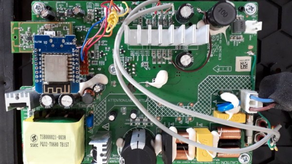
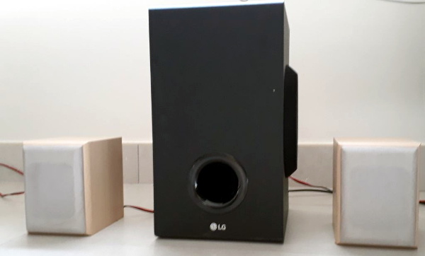
As a perfect example, [Acuario] recently discovered that the LG SJ2 sound bar has quite a few features that aren’t advertised on the box. Whether it’s due to greed or just laziness, it turns out LG isn’t using many of the capabilities offered by the ESMT AD83586B IC inside the amplifier. The chip gets its configuration via I2C, so thanks to the addition of an ESP8266, the expanded capabilities can now be easily enabled through a web interface.
[Acuario] has already found out how to turn on things like simulated surround sound, or per-channel volume controls; all functions which aren’t even exposed through the normal controls on the sound bar. But it goes deeper than that. The LG SJ2 is a 2.1 channel system, with a wireless speaker providing the right and left channels. But the AD83586B inside the subwoofer is actually capable of driving two locally connected speakers, though you obviously need to do a little rewiring.
There are still even more capabilities to unlock, though [Acuario] is currently struggling with some incomplete documentation. The datasheet says there’s support for user-defined equalizer settings, but no examples are given for how to actually do it. If anyone’s got a particular affinity for these sort of amplifier chips, now could be your time to shine.
What’s the weirdest computer you can think of? This one’s weirder.
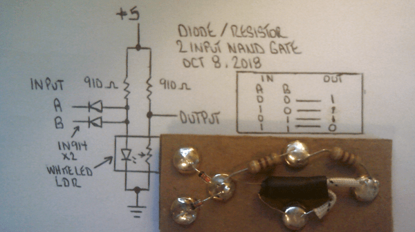
[Dr. Cockroach] figured out a way to create an inverting NOT gate from just one LED and two resistors (one being a photo-resistor). The Dr. has since built AND, NAND, OR, NOR, XOR and XNOR gates, as well as a buffer, incorporating light into every logic gate.
Traditional inverters – NOT gates – are already made with diodes (typically not light-emitting), resistors (typically not light-dependent), and bipolar transistors. The challenge was to reduce the number of transistors. The schematic from the very first test shows the slight modifications [Dr. Cockroach] made to incorporate light into the logic gate using a 910 Ohm, output LED, and an LED and LDR in parallel.
The output is initially 4.5V for logic 1 and 1.5V for logic 0. Adding two 1N914 diodes and an AND gate ahead of the inverter create a two-input NAND gate. With the two diodes reversed and a 910 Ohm resistor removed, a NOR gate is created.
The next step was to build a S-R latch using the NAND gates and inverters, which holds some basic memory. From there, with some size reductions, a Master-Slave J-K Flip Flop, similarly using NAND gates and inverters, can be built. The current state of the project is a working sequencer and counter. You can even see a smooth sine wave propagating through the LED chaser, which is typically built with ICs or transistors but in this case is built simply with LEDs, LDRs, resistors, and capacitors.
The upcoming plan is to use the gates to build a processor that only uses diodes, resistors, and capacitors. While it’s probably not going to be nearly as fast as any processors we have today, it should be interesting (and educational!) to be able to visually track the flow of data from one logic gate over to the next. Continue reading “Light Emitting Logic Gates Built From Scratch”→
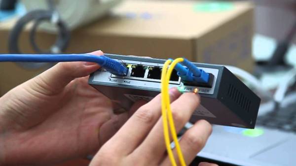
A remote Ethernet device needs two things: power and Ethernet. You might think that this also means two cables, a beefy one to carry the current needed to run the thing, and thin little twisted pairs for the data. But no!
Power over Ethernet (PoE) allows you to transmit power and data over to network devices. It does this through a twisted pair Ethernet cabling, which allows a single cable to drive the two connections. The main advantage of using PoE as opposed to having separate lines for power and data is to simplify the process of installation – there’s fewer cables to keep track of and purchase. For smaller offices, the hassle of having to wire new circuits or a transformer for converted AC to DC can be annoying.
PoE can also be an advantage in cases where power is not easily accessible or where additional wiring simply is not an option. Ethernet cables are often run in the ceiling, while power runs near the floor. Furthermore, PoE is protected from overload, short circuiting, and delivers power safely. No additional power supplies are necessary since the power is supplied centrally, and scaling the power delivery becomes a lot easier.
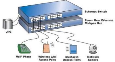
Devices Using PoE
[via PowerOverEthernet.com]VoIP phones are becoming increasingly prevalent as offices are opting to provide power for phones from a central supply rather than hosting smaller power supplies to supply separate phones. Smart cameras – or IP cameras – already use Ethernet to deliver video data, so using PoE simplifies the installation process. Wireless access points can be easily connected to Ethernet through a main router, which is more convenient than seeking out separate power supplies.
Other devices that use PoE include RFID readers, IPTV decoders, access control systems, and occasionally even wall clocks. If it already uses Ethernet, and it doesn’t draw too much power, it’s a good candidate for PoE.
On the supply side, given that the majority of devices that use PoE are in some form networking devices, it makes sense that the main device to provide power to a PoE system would be the Ethernet switch. Another option is to use a PoE injector, which works with non-PoE switches to ensure that the device is able to receive power from another source than the switch.
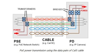
How it Works
Historically, PoE was implemented by simply hooking extra lines up to a DC power supply. Early power injectors did not provide any intelligent protocol, simply injecting power into a system. The most common method was to power a pair of wires not utilized by 100Base-TX Ethernet. This could easily destroy devices not designed to accept power, however. The IEEE 802.3 working group started their first official PoE project in 1999, titled the IEE 802.3af.
[via Fiber Optic Communication]This standard delivered up to 13 W to a powered device, utilizing two of the four twisted pairs in Ethernet cabling. This was adequate power for VoIP phones, IP cameras, door access control units, and other devices. In 2009, the IEEE 802.3 working group released the second PoE standard, IEEE 802.3at. This added a power class that could deliver up to 25.5 W, allowing for pan and tilt cameras to use the technology.
While further standards haven’t been released, proprietary technologies have used the PoE term to describe their methods of power delivery. A new project from the IEEE 802.3 working group was the 2018 released IEEE 802.3bt standard that utilizes all four twisted pairs to deliver up to 71 W to a powered device.
But this power comes at a cost: Ethernet cables simply don’t have the conductive cross-section that power cables do, and resistive losses are higher. Because power loss in a cable is proportional to the squared current, PoE systems minimize the current by using higher voltages, from 40 V to 60 V, which is then converted down in the receiving device. Even so, PoE specs allow for 15% power loss in the cable itself. For instance, your 12 W remote device might draw 14 W at the wall, with the remaining 2 W heating up your crawlspace. The proposed 70 W IEEE 802.3bt standard can put as much as 30 W of heat into the wires.
The bigger problem is typically insufficient power. The 802.4af PoE standard maximum power output is below 15.4 W (13 W delivered), which is enough to provide power for most networking devices. For higher power consumption devices, such as network PTZ cameras, this isn’t the case.
Although maximum power supply is specified in the standards, having a supply that supplied more power is necessary will not affect the performance of the device. The device will draw as much current as necessary to operate, so there is no risk of overload, just hot wires.
So PoE isn’t without its tradeoffs. Nevertheless, there’s certainly a lot of advantages to accepting PoE for devices, and of course we welcome a world with fewer wires. It’s fantastic for routers, phones, and their friends. But when your power-hungry devices are keeping you warm at night, it’s probably time to plug them into the wall.
Unless you live in a special, unique place like Hawaii or Costa Rica it’s unlikely you’ll be able to surf every day. It’s not easy to plan surf sessions or even surf trips to most locations because the weather conditions will need to be just right. Not only the wave height (swell) but also the wind speed and direction, tide, water and air temperature, and even amount and type of marine life present can all impact your surf session. You’ll want something which can easily tell you right away if conditions are good.
This project from [luke] is called the Surf Window shows the surf conditions at the local beach with just one glance. Made out of various pieces of wood, each part represents one of the weather conditions at the beach. A rotating seagull gives the wind direction, for example, and the wave height is represented by 3D, moving waves. All of the parts are connected with various motors and linkages to an Arduino Mega +WiFi R3 which grabs all of its information from Magicseaweed, a surf forecasting site.
The Surf Window can show the current conditions at virtually any surfable beach in the world, so if you really want to know how Jaws, Mavericks, or even Reef Road is breaking right now, you could use this to give you a more nuanced look. Don’t forget to take the correct board for the conditions!