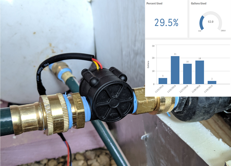
There’s almost always more than one way to get any particular job done. Suppose for instance you have a tank you fill up from a well, and you’d like to know when the time is right to refill the tank. The obvious answer is to measure the level of the tank, and there are plenty of ways to do that. However, [Liam Hanninen] has a different approach. Using a flow meter, he measures how much water leaves the tank. Assuming that you know it was once full, you can deduce how much water is left.
Using a YF-S201 flowmeter on a Raspberry Pi, the code uses Python to populate a database. The meter will need to be calibrated to get an exact volume measurement.
There are many ways to measure flow. The YF-S201 uses hall effect sensors to measure the Yrotation of what amounts to a waterwheel. It counts the clicks of the wheel as the water turns it. However, there are many other possible types of flowmeters including those that measure the electric current generated by a slightly conductive fluid moving through a magnetic field. Other flow meters measure the cooling of a moving fluid across a hot wire.
Monitoring a tank level is a pretty common task. The tank doesn’t always hold water, though.


The way they measure the water in a municipal water tower is by measuring the water pressure with an analog pressure meter connected to the pipe that runs to the tank. The meter has a mechanical switch with an adjustable setpoint which turns on /off the fill pump motor. The meter is set below the base of the water tank, but typically is mounted at eye level in the pump room.
A problem I can see with measurements of goes-into vs goes-outo volume is the error of the calibration infinitesimals, where there is slightly more vane leakage on fill vs drain due to head pressure and the system will eventually think the tank is full when it isn’t.
Yep and there are other factors, there should ALWAYS be a level meter on a water tank, whether its stop-cock, float etc. at least for redundancy if the flow meter fails, isn’t calibrated correctly or real world issues occur. I only hope they’ve got an overflow on the tank or a cutoff on their heating/powershowers for when the level is too low.
If you have a dripping faucet or a leaky toilet, you can lose water at a rate that simply doesn’t register with the flow meter. Then there’s the occasional air bubble or debris in the water line, or pressure wave effects that cause the meter to spin back a revolution or two… It basically cannot be calibrated completely accurately and there will be drift.
Or you could put a ping pong ball with a small magnet attached into a tube that you plumb into the bottom of the tank (leaving the top open) at the appropriate low level you mount either a reed switch or a hall effect sensor and none of the above power wasting calculation error prone shickanery needed. Ofcourse if you use a clear tube you can see the level at a glance but no one will blame you if you use the sensor to trigger a ….. 555 …. for some flashing light effects or perhaps an rf pattern generation like a rf code based garage door transmitter so you can receive, decode and log the event to your hearts content. You could also add 1/3, 2/3rds and full sensors to get better accuracy or as many as you like.
Just install the tube, cut a notch on the other end, and mount the pistol from an air hose next to it.
Squeeze the trigger and listen to the level by the hoot that it makes.
boy I like the sound of that
Use Ultrasonic Flowmeters if possible, as this is non-invasive on whatever you’re trying to measure the flow of.
I always wonder how cars do it – my car tells me my current usage (mpg) and estimates the range I have left. I’m certain the former is done by a flow meter as above, but how is the range estimated with any sort of accuracy? There’s obviously a fuel gauge but I’ve never put much stock in it for accurate readout, so is the range estimation based on some other measure of fuel (flow-in/flow out or float) or is it again just pretty inaccurate?
The car controller knows exactly how much each injector is pumping into each cylinder, so the flow measure is very accurate. The range estimate is calculated by dividing the estimated residual fuel by the average fuel usage of the last 20 to 30 km of travel. It’s not terribly precise but usually good enough for common scenarios. I think it relies on the tank meter to be somewhat accurate, which really messed me up once.
It’s not that accurate in reality since the volume of the injectors isn’t known to the microliter and the amount of time they actually stay open on command isn’t known to the ECU. There’s variation and wear, and the fuel has a different density depending on temperature. The computer has a fuel injection map that is based on some sort of theoretical calculation, and it homes in the rest by observing the oxygen sensor – it knows how much should be going in, but it doesn’t know whether that’s actually happening.
In older cars the dashboard computer estimated the fuel use by the throttle body air mass sensor, with the assumption that however much air is going in, that much fuel must also be going in. It was somewhat accurate.
The car’s ECU knows the duty cycle of the injectors and the fuel pressure. From this it can calculate fuel burn in grams per minute (or whatever units you want)
The other part of the puzzle would be knowing exactly how much fuel is left in the tank. Maybe the sensor for that is actually really accurate? It could probably be reset every time you top off the tank, and ECUs tend to have pretty good self learning (e.g, changing mixture ratios to compensate for different octane fuel or driving style)
This is how I monitored the level in an outside heating oil tank. The furnace had a 1 gal/hour nozzle and I used a resettable AC hour meter, attached in parallel with the burner. When the burner was on, the meter was running. I knew the tank capacity, and reset the meter every time the tank was filled. When the reading came close to the tank capacity, I called for a delivery.
As Nick said, the ECU has pretty detailed knowledge of exactly how much fuel is being consumed by the engine at any moment in time. The other side of that is the tank level. In most passenger vehicles I’ve dealt with, the fuel tank level sensor is part of the fuel pump tower, and is essentially an arm with a float on the end, which is attached to some manner of sensor that can monitor the angle of the arm, and hence the level of the tank. The manufacturers obviously have to calibrate this sensor reading based on the tank size/dimensions, as the change in physical level vs tank capacity can vary over the course of draining the tank due to the unusual geometries of a typical fuel tank.
Then you add in a safety margin. The systems are designed to underestimate the fuel remaining by enough of a margin that you can typically still get 10-20 miles, because, well, lazy humans can always be counted on to push the limits of any system they engage with, and nobody likes running out of gas a few miles short of the next station.
The fuel pump gets damaged if it runs dry, and that then creates interesting problems.
What commonly happens is, the person runs the tank dry and the pump runs out of liquid, and the vanes get damaged slightly. The driver fills up the car again, drives on, then runs out again, the pump gets damaged a little more. Eventually if not the first time already, it starts leaking backwards slightly and the engine is starved of fuel and starts behaving weirdly – especially under hard acceleration. The driver then spends tons of money with garages who “diagnose” the engine, swapping out parts that they don’t need to, and the owner ends up cursing the car’s brand and calling the manufacturer a piece of **** before they finally figure out what the problem was.
So it’s more of a safety for the car and the manufacturer rather than the driver. They don’t want the reputation.
The fuel flow is derived from the air-flow sensor measurements (usually calibrated when installed) and the air/fuel ratio. Injectors tend to wear or vary their flow-rate as they age. Range is determined from the tank level and is only approximate. (I have a car converted to use propane as well as pump-gas and the range doesn’t fall when running on propane, it can sometimes go up when driving under the right conditions.)
A solution like this will eventually suffer from integration errors. All flowmeters have some amount of DC offset and nonlinearities (as in, some value epsilon which is necessarily nonzero, but likely close to zero), and integrating them will eventually result in an error which increases toward infinity over time (possibly a long time). It is possible to reset it when the tank is empty/full (some old laptop battery controllers suffered from this problem, which resulted in the age old remedy of allowing the laptop to completely discharge and then letting it fully recharge to re-calibrate its current sensor) but in a situation like this it is much more accurate to instead put a pressure transducer at the bottom of the tank. The pressure is directly proportional to the liquid level in an open tank, so this gives a direct reading of the level, which is free from accumulated drifts (to within the drift specification of the gauge).
An automotive oil pressure sensor type unit can be had for about $10 and give a level reading from 0 to 20m and last for decades.
This solution seems to work for his use case, likely because he is able to fill the tank ‘full’ to reset it every cycle. But something to consider if you do not have a integral reset strategy.
This. Also, the power to your measuring device will fail at some point, or it will crash, in which cases you always lose calibration.
automotive oil pressure sensor sounds interesting!
Do you by chance have an example for this application of such a sensor? Do they have a port hole or a delicate membrane? What happens if you deploy them in water instead of oil, will they rust? Engine oil pressure is measured after the oil filter, so there are no particles in the oil. I cannot say this about the rainwater my cistern, especially in the fall when the filter is sometimes overflooded, and not about the zone on the ground because every 3..5 years I have to clean out sediments.
My tank is a irregular shaped cistern in the ground made from concrete, so I do not have threaded ports to screw a sensor in from the outside.
I was thinking of building something like https://lukemiller.org/index.php/2014/08/open-wave-height-logger/ and place it at the ground with sth. like a cinder block as an anchor or weight, but have no clue on how to make it waterproof over long times.
Here is one on amazon with a stainless steel body that is specified for water duty an runs on 5v so should be compatible with your system. Automotive duty ones usually a metal membrane, but who knows when you are getting when you order “Wal front” brand. You can screw it into the plumbing anywhere upstream of the valve, just don’t forget that any head between the valve and the tank doesn’t count for your tank capacity. If you are really paranoid you can leave a bit of an air space under the sensor (ie, vertical tube terminating into the sensor) to prevent the water from coming in direct contact with the sensor.
https://www.amazon.com/Pressure-Transducer-0-5-4-5V-Transmitter-0-10PSI/dp/B07KJHRPLG/
If you want to invest in a proper sensor, industrial versions come in the range of $100-200 but then you can select exactly what you want for the thing. You can pick digital/analog signals, absolute/ratiometric, how much supply voltage, how much pressure, stainless steel everything, custom cable length…
Example:
https://www.impress-sensors.co.uk/products/sensor-products/pressure-measurement/oem-pressure-transmitters/IMTG-OEM-Submersible-level-transmitter.html
That’s a submersible sensor you can just dunk in the tank. It comes with threads, so you can install it in a port if you want to.
And the threaded stud comes with a port hole just like the oil pressure sensors… Maybe I should get some from the junk yard and tear one down.
I wouldn’t mind the 100 bucks if that problem is solved then. The cistern is not easyly accessed.
Thank you!
For a DIY solution, there’s some simple sensors you can use.
A stainless steel tube with plastic end caps drilled with holes, and an enameled copper wire strung through the middle of the tube can serve as a capacitance level sensor. You simply measure the capacitance between the tube and the wire.
That may be done with a multimeter, or some sort of RC oscillator run by an Arduino. The capacitance of the tube changes by a factor of 80 when it’s full of water, and goes down more or less linearly when it’s partially full.
And it will over time get a biofilm – a slightly slimy layer of unicell organisms. If you ever have been in an unserviced swimming pool then you know what I mean.
I’ve given up on anything with electricity directly in water. Please do not forget: rainwater is NOT distilled water any more, because it ran over your roof(s) before, and birds do neither wash their feet nor wipe their a… ;)
An alternative idea popped up while attending my biweekly “beer annihilating meeting”:
– have a swimmer/buoy on the water surface (easy)
– have it attached to a crossbar expansion joint (pantograph? not sure… pls. image-google for “scherenauszug”) which hangs from the manhole lid (easy, parts supplied by swedish furniture gigant)
– use the cheapest of 3axis gyro sensors with I2C to measure the angle of the uppermost bar of the crossbar expansion joint (I saw ones from bar angle is proportional to buoy height (=water height)
=> mapping the height value with an array of areas (cistern ist irregularly shaped) should give me a volume value
I hope the idea is convincing tomorrow morning :)
I hate it when using parentheses and euro sign eats one and a half sentences.
I’ve been using that flow meter to help automate my rain collection and purification system for years. They do fail now and then. They are no where near accurate enough to keep real track of tank level over any time span. They are handy to help with control – for example, if you open an inlet valve and there’s no flow – shut the valve, there’s no point, and if it’s a solenoid valve, why make it hot?
Level is best detected by something that actually detects level. Most schemes I’ve tried last under a year – corrosion, “stuff growing on the float jamming it” – you name it, they fail. Since this is for my living quarters, even a failure a year that causes a couple trips to the “bang your head crawlspace” is too few nines.
I finally settled on a scheme that uses the dielectric constant of water, and titanium wire electrodes, and that’s been perfect for over 5 years now – even with “fur” goring on the wires in the basement cistern.
Yes, it uses a 555 to drive one electrode that goes along the tank bottom with a big 50khz square wave. Other electrodes that come down from the top to different heights are connected to small AC coupled voltage doublers with ~ 100k ohm load. This works out to making a logic level into an arduino when the water level touches an electrode, which is read in and reported to a raspberry pi home master that produces things like web pages to show and control stuff.
This shows NO SIGNS WHATEVER of ever failing. Zero galvanic current, titanium used in fresh water. This and other linked threads on my site describe a version I’ve implemented. I’ve since changed that arduino in the basement to an ESP8266, and redone the pi master, but that’s more for elegance than function. http://www.coultersmithing.com/forums/viewtopic.php?f=59&t=1119&start=0
Sounds like a great recipe for a Gimli Glider style failure
Whats wrong with two float switches?
One at top of tank and one near bottom of tank.
Am I over thinking it ?