As the open-source movement has brought its influence to more and more fields, we’ve seen an astonishing variety of things once only available at significant expense become accessible to anyone with access to the tools required to create them. One such arena is that of scientific instrumentation, and though we have seen many interesting developments there has been one which has so far evaded us. An analytical balance, a very specialised weighing machine designed to measure the tiniest of masses, remains available only as a new unit costing a fortune, or as a second-hand one with uncertain history and possible contamination. Fortunately, friend of Hackaday [Zach Fredin] is on the case, and as part of one of his MIT courses he chose to create an open-source analytical balance.
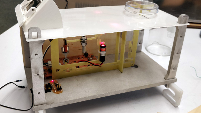
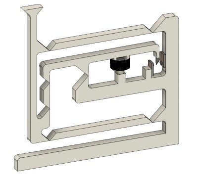 The write-up is interspersed with his course notes as he learns a series of fabrication techniques, but in addition to the milled Delrin finished model he treats us to his prototype and gives us an explanation of how these instruments work. It’s a technique that’s rather different to a traditional weighing machine: instead of measuring deformation of a spring in some way it produces a force from an electromagnet to oppose that exerted by gravity on the mass to be measured, and quantifies how much electrical energy is required to do that. The mechanism incorporates feedback through a vane and an optical sensor, which he admits he’s not yet had time to set up properly.
It’s an interesting project not least because it exposes some of the inner workings of an analytical balance, and we look forward to his completing it. If this whet your appetite for the topic it’s worth also looking at [Ben Krasnow’s] video of a balance made using a moving coil meter for an explanation of the technique.


Wow, just wow!
“it produces a force from an electromagnet to oppose that exerted by gravity on the mass to be measured, ”
That reminds me of Fluke Voltmeters of 40 years ago, where you matched the voltage you were measuring by adding voltages (at ever decreasing amounts through various decade resistances) until you centered the needle in the middle of the movement. Then you read out the numbers on the decade switches.
Wheatstone bridge?
Exactly. The front panel was basically a huge decade resistor and a mechanical meter, but it also used an instrumentation amp to get high input impedance. Look up Fluke 801. It was a 6-digit voltmeter before this was really possible any other way. Except I remember a meter from Non-Linear Systems in San Diego, that used telephone stepper relays to automate the process, and incandescent edge-lit acrylic displays.
I recall a magazine article from about 40 years ago that used a zero-center microammeter to make a balance. The pointer of the meter was twisted 90 degrees and used as the sample tray (for very small samples). The meter was positioned on its side. When the sample was placed on the tray, the weight of the sample deflected the needle. A small DC current was put through the meter to bring the needle back to the reference position. The current was proportional to the mass of the object.
Ok, this is pretty damn impressive and cool.
This is how many electronic/digital scales worked before good load cells became available during the 1980’s. The design of the linkages and the use of flexures here is quite nice.
The traditional devices used clamped metal strips for flexures– Some of the ones I still have around at work seem to be stainless steel, but I have seen carbon steel (which is very subject to corrosion) and bronze, as well. I should guess that other materials have been used.
Force balance vertical seismometers employ this method to measure earthquakes.
Also known as the Anakin Effect, theorized to bring Balance to the Force.
These are the kind of projects that keep me returning to Hackaday.
Jenny- he made a desktop wire EDM machine too- WOW.
Id love to hear more about this from him!
http://fab.cba.mit.edu/classes/865.15/people/will.langford/11_final/index.html
That makes me drool
not me — my predecessor Will! another project to finish..
Looking forward to it!
You are both pretty awesome, and your projects are inspiring. I didn’t know MIT people actually built specialized equipment like this. I see disconnects between engineers and machinists as normal- so I always wondered where the maker engineers were.
If I had had a chance to do stuff like this when I was still an engineering student at a major 4 year university, I might have stayed with it instead of becoming a language specialist then a machinist/watchmaker.
The world needs more high level discipline synthesis like this- it makes for truly incredible projects
Its not same person.. Zach Fredin made this, Will Langford made that EDM. Not that its not cool, but just wanted to highlight its different person.
Maybe use a linear sensor from a scanner or a sensor from an optical mouse and some lenses to spread a light out. Then stack a few razor blades like jenga blocks to make a really fine line to measure the position of. A mirror on the balance’s armature could increase the accuracy even further.
Perhaps you could even weigh gravity with it and sense cars passing outside.
^^^ measure.
IIRC, this was at least for a while (and maybe currently – no pun intended) the method of providing a primary standard for the Ampere.