[James Bruton] OpenDog remains one of the most impressive home-built robotics projects we’ve seen here on Hackaday, and it’s a gift that just keeps on giving. This time he’s working on adding force sensing capabilities to OpenDog’s legs to allow for more dynamic movement control.
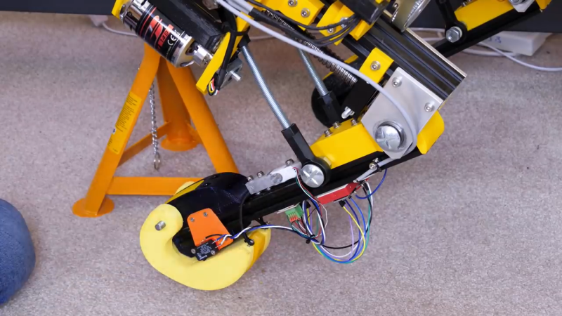
The actuators in the legs are three-phase outrunner motors that drive ball-screws via a belt. This configuration is non-backdrivable, meaning the legs cannot be moved when an external force is, which could lead to mechanical failures. He as tested other backdrivable leg configurations with other robots, but did not want to rebuild OpenDog completely. The solution [James] went with is a redesigned foot with an inbuilt switch, to confirm that the foot is touching the ground, and a load cell attached in the middle of the bottom leg segment. The load cell is bolted rigidly onto the leg segment, which allows it to sense when the leg is carrying load, without damaging the load cell itself.
Unfortunately all the serial ports on OpenDog’s main Teensy 3.6 controller are already used, so he converted the signal from the load cell to PWM, to allow it to be read by a normal GPIO pin. This works well in isolation, but when [James] switches on the motors, the PWM signal from the load sensor gets flooded by interference, making it unreadable. To solve this problem, he wants to implement a CAN bus, which will allow for more inputs and outputs and hopefully solve the interference problem. However, [James] has no experience with the CAN protocol, so learning to use it is going to be a project on its own.
OpenDog is turning into a very lengthy, time-consuming project, [James] says that the lessons learned from it have been invaluable for a number of other projects. This is something to keep in mind with everything we tackle. Choose projects were the experience gained and/or relationships developed are worth it on their own, even when the project fails in a conventional sense. This way you can never really lose.


It’s an impressive tour de force of robot design, a proof that anything can work if you only install enough Arduinos in it.
Instead of a load cell, a much simpler solution is to have TWO switches on each foot. One closes when the foot has any load on the foot at all (foot has hit ground), and the other one has a bigger resistance and fires when the force applied to the foot is greater than or equal to the weight of, say, 50% of the robot. That switch is the “we need to lift the foot or we’ll be damaged” sensor.
But then you’d also need to add additional sensors so it could detect it was wearing socks/bootees in order to know to take extra high steps.
You don’t need external load cell. You can simply superglue strain gauge directly to the aluminum extrusion, thus turning whole thing into custom strain gauge…
It’s better than two switches, because PID control works much better with analog inputs and you can calibrate it in software. You would need to physicaly calibrate some spring tension in order to achieve what you suggest.
Though really, you don’t need load cells because they’re already built in. The motors… just wiggle them a bit, measure current.
I don’t think that would work with ball screw driven legs.
Well that’s why you have to wiggle them, they’re not holding on stall current.
One option that could be tried if there’s enough analogue inputs… 4-20mA current loop. Even a differential-output op-amp driving twisted pair may work here. These will be simpler solutions than CANbus.
As for CANbus… some points
:
– if you can use a built-in CANbus peripheral, that should be used in preference to external ones like the Philips SJA1000 or Microchip MCP2515
– There are USB CANbus dongles which are really handy for debugging these things. Many will work under Linux, e.g. the Lawicel CANUSB which is basically a SJA1000 bolted to a FTDI serial I/O chip. slattach pointed at the appropriate USB port usually gets them going. Writing CANbus software using Linux’s SocketCAN is like writing UDP applications with a really tiny MTU.
– In my experience, I found the MCP2515 wasn’t too bad to drive, but in high-traffic situations, I found it was possible for an incoming packet to overwrite the payload of a packet it was about to send. I didn’t have a logic analyser to debug this fully (this was 2009, kit was more expensive then) but I was able to reliably reproduce the problem which I found quite alarming. In our case, the MCP2515 was controlling a 20kW BLDC motor controller, and the problem showed up as very distinct “tick” due to the motor being asked to spin up to some random speed then immediately stop at 0 RPM. We cured this by replacing the MSP430F143+MCP2515 with a Luminary Micro Cortex M3 which had CANbus built-in.
– With CANbus, the controller is a full-duplex device, it’ll listen on the bus as it sends out its traffic, the controller if it senses a disparity, assumes it has lost arbitration and will back off. Without a transceiver, the controller will think it never has arbitration of the bus.
– Numerically lower IDs have higher priority. (“0″s are “dominant”, “1”s are “recessive”). I’d start by say assigning the MSB of the ID as being the message type, say 0 for control, 1 for status; then assign your other bits bearing in mind relative importance.
The last project I worked on with CANbus was an electric harvester platform (which I think wound up taking swimming lessons in the 2011 floods that hit the Lockyer Valley)… there we used 11-bit addressing to control 4 independently steerable wheels, two of which had 20kW BLDC motor controllers.
The protocol I wound up using was based on what Tridium were using (the traction motor controllers were basically Tridium controllers hacked to work on 48V DC with MOSFETs instead of 600V DC with IBGTs). Their protocol used 5 LSBs of the ID to represent the “property”, with the upper 6 bits being a device ID which was arbitrarily set.
I kept the lower 5 bits as they were (giving me 32 possible properties per device), assigned the MSB as being steering/traction (0=steering, 1=traction); then the next bit as status/control (0=control, 1=status), leaving the remaining 4 bits to address an individual wheel assembly (traction + steering controllers). Rationale being that control of direction is more important than control of speed, and that commands should have priority over status.
A similar approach could work for OpenDog, assigning different bits to prioritise certain parts of the leg. You might decide that more properties are needed, you’ve got the luxury in that OpenDog is completely green-fields.
The payload of the message can be a maximum of 8 bytes. I found I was able to do block-wise transfers with some crude protocol to send 4 bytes at a time, but right up front you’re going to want to pay careful attention to what data you want to send and how to format it because there isn’t much space in a CANbus packet.
Looks like you have the canbus all figured out.
CANbus was a big part of my final year project at uni.
Title for bots:
Load cells, or how to use the force when you are not a Jedi
:o)
@ Hackaday: Pleasy try to also add a link to the main website of projects (if there is one) such as
http://www.xrobots.co.uk/
I had a quick look at oDrive, and was surprised these controllers do not have some integrated networked interface.
They seem to have USB, so you could use a USBhub to connect a bunch to some intelligence circuit, but USB is not really fit for industrial applications, but apparently CAN is “Coming soon” https://odriverobotics.com/#features
You can also glean on Ananasstepper, which is a project that also uses CAN for motor control:
https://hackaday.io/project/20980-ananasstepper-20-30
(And there are more).
As a quick / temporary solution for the noise on your PWM signal, It probably helps to put a small RC filter on the signal on the side of the cable where it is read by a uC. RC time should be so small as to not seriously distort the PWM signal, but just to filter out short glitches. (RC time of 10us or so). You can also route the cables through the aluminimum profiles. This does not only look better and protect the cables, but also shields them from interference if you electrically connect the aluminimum profiles to your GND.
PWM? CAN? Run that I2C stuff in parallel, one GPIO for a shared clock and one GPIO for each data line.
I2C was never ment to, nor designed for leaving a PCB.
It’s sole purpose was to ease the wiring on a single PCB.
It is not reliable once you start putting it through cables, especially in high noise environments such as close to these motors and motor controllers.
People who tell you otherwise just got lucky with their application.
CAN and RS485 are robust (if designed properly) and specifically designed to be used in electrically noisy environments.
Well, then Philips got lucky with billions of TVs and VCRs, which often had a bus length >1m running thru multiple boards and wires (and CRT-based TVs are a very noisy environment). I2C can be pretty robust if one follows the design guidelines in the official specs.
It depends on your definition of “pretty robust”. It wil never be anywhere near CAN nor RS485.
And Indeed, I admit I2C still works in a small system with a few PCB’s (Philips has long ago written an AN with guidelines for I2C over a flatcable.)
But even apart from reliability, the passive pullups of I2C will make communications at least slow because of wiring capacitance. I2C can work upto a few meters, but you’re really stretching the limits of I2C.
Suppose you want to add some smart sensor nodes in the feet of RoboDog later. That’s the length of 4 legs, each 70cm or so of wiring and the “spine”, so wiring would already be > 3m. Then add a few loops for going around PCB’s and in joints.
RS485 and CAN transceivers also have much higher ESD immunity than I2C, which is usually just uC I/O pins. During development such as this project, connectors get (dis-) connected a lot of times. Wires get pinched and broken, shorted, or inadvertently higher power supply voltages get injected into the bus wires. Both CAN and RS485 have a good chance of surviving all these events. I2C does not.
This is a completely different environment from a TV designed by a team of experts and then screwed closed and not being supposed to be opened (in normal use).
On top of that, I2C is also not a simple bus. Interfacing a few sensors with a uC on a single I2C bus is pretty trivial, but adding multiple uC’s to the bus (not even speaking of multi master mode), when bus arbitration starts getting important, you start getting into an area where lots of I2C libraries are only partially implemented, and uC’s with badly implemented I2C peripherals or even hardware bugs. There are quite a lot of edge conditions. One of the most irritating is the infinite clock stretch option. This (or other software stack errors) are often the cause of the whole I2C bus hangs.
Compare this with CAN, which often has built in options to stop “babbling idiots”, either by releasing the bus, or by resetting the idiot.
When designing a project such as RoboDog it’s much better to simply avoid I2C (except as a local bus) and implement a more robust bus, then to find out later that it’s only marginally usable.