If a grizzled RF engineer who bears the soldering-iron scars of a thousand projects could offer any advice, it would be that microwave antennas are not a field to be entered into lightly. Much heartache is to be saved by using an off-the-shelf design, and only the foolhardy venture willingly down the stripline into the underworld of complex microwave resonances.
But every would-be microwave designer has to start somewhere, and for [Adam Gulyas] that start came with a 2.4 GHz patch antenna. His write-up is a fascinating tale of the challenges and pitfalls of creating something which is deceptively simple at first sight but which becomes significantly more complex as he characterizes his design made real as a PCB.
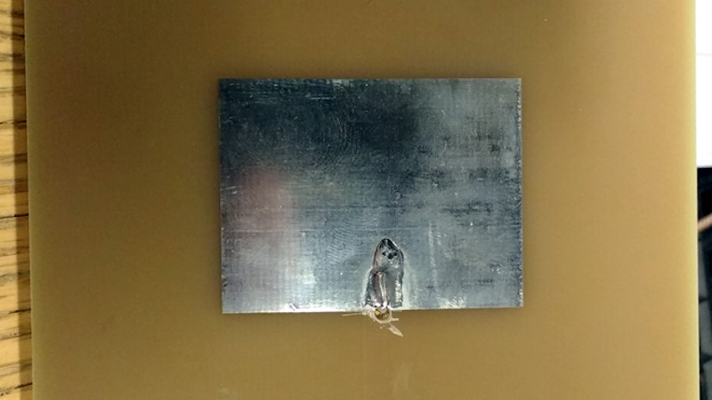
The process started with a set of calculations to derive the patch dimensions and a bit of PCB work adding a stripline feed. This was produced on a PCB, a normal 1.6mm thick FR4 fiberglass board. When hooked up to a VNA its impedance was all wrong. Further, it had a resonance at the required frequency but also unexpected ones at 3.7 and 4.6 GHz. Simulation of the design also yielded a different resonance from the one calculated, and discussing it with others yielded the conclusion that the feed might be at fault. He ended up using an inset feed, with a co-axial cable emerging away from the edge of the patch, and was able to achieve a far better result.
We can all learn something from [Adam]’s write-up, and we salute him for staying the course to get the design to a usable point. It would be interesting to see the same antenna produced from a more consistent dielectric material than generic FR4. Meanwhile, if you are interested in microwave RF design, take a look at Michael Ossmann’s primer on the subject.


Remember kiddies, speed of light and dielectric constant may vary wildly between materials…. so when you jig up that perfect length of mini coax and use that length on your fibreglass PCB, el problemo is in the building.
Skin effect seem essential in lead-free solder joint at frequency about 1 Mhz.
https://ieeexplore.ieee.org/document/6231459
So some type of solder alloys as well might be a problem.
Yes, Rekt Tangle.
microwave stuff is straight up magic.
Fr4 is not great beyond 1GHz out so. It gets lossy.
We use Fr4 up to 8GHz,without much problem. Have to be extra careful with connections and impedance matching, but with the right simulation tools and good quality manufacturing its possible
Indeed, although a patch antenna is a resonant structure with the high loss FR-4 in between. It will work, but the efficiency will degrade. Maybe an air-gap patch antenna will work better?
There are designs on FR-4 which go upto 10GHz without much loss. Only catch is antenna has not to be a patch antenna.
I’ll stick with bi-quads. never had any luck with patches.
i’ll stick with double bi-quads.
my favorite one I’ve built so far is a double biquad yagi.
I realize that I will be doing this later in the semester. I am both terrified and excited all at once. I might jump back to this for practical tips on how to succeed with patch antenna design.
If you only need to make one or two, I advice requesting a sample of a proper RF substrate from Rogers and using that – the dielectric will be much better controlled. I also recommend designing it for a slightly lower frequency and tuning it with a razor blade. By trimming off the edge, you will raise the resonant frequency.
Good tips to keep in mind! I haven’t gotten the lab assignment for the patch antenna yet, but this sound similar to tips my professor has given for our Yagi-Uda antennas and LPDA’s. For the Yagi, he suggested making the driven dipole slightly longer than needed and slowly shaving it down, while for the LPDA he suggested using nylon nuts to separate the two booms so we could play around with the spacing to get the best impedance match.
They use inverted F on a stamped pieces of metal for the antennae (2.4 and 5GHz) on my routers. That got around having to deal with the lossy FR4 dielectric.
The match at 2.4 GHz can be better. You I aim for better than -10 dB. By adjusting the probe position closer to center (or maybe closer to the edge) the impedance the probe is changed resulting in a better patch.
Never feed it in the center, the impedance is zero at the center of the patch. You have to feed it in between L/6 to L/4 where L is the length of the patch.
They are very much easy till you make simple patch antennas , once we enter dual and massive Patch array then there I can say it is all art.
The patch and substrate material are both fine. The problem is that the feed is at the edge where the impedance is high. What’s needed is a ‘pin feed’ near (but not at) the middle. Also, 1.6mm of FR4 is a bit thin and lossy – the patch could work better still if the board were made thicker, or separated from the ground plane with air (but of course then the patch size would have to be adjusted to account for the lower dielectric). It’s not magic. :)
All I know about resonant structure matching I learned from pushing kids on swings.