Unless you work for the government or a large corporation, constrained designs are a fact of life. No matter what you’re building, there’s likely going to be a limit to the time, money, space, or materials you can work with. That’s good news, though, because constrained projects tend to be interesting projects, like this airborne polarimetric synthetic aperture radar.
If none of those terms make much sense to you, don’t worry too much. As [Henrik Forstén] explains, synthetic aperture radar is just a way to make a small radar antenna appear to be much larger, increasing its angular resolution. This is accomplished by moving the antenna across a relatively static target and doing some math to correlate the returned signal with the antenna position. We saw this with his earlier bicycle-mounted SAR.
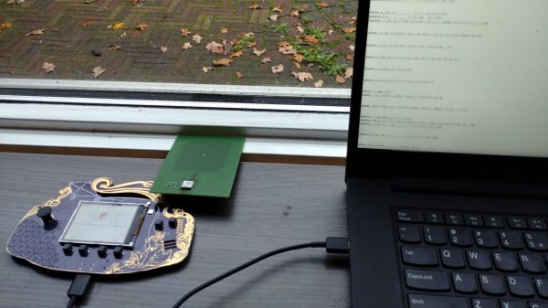
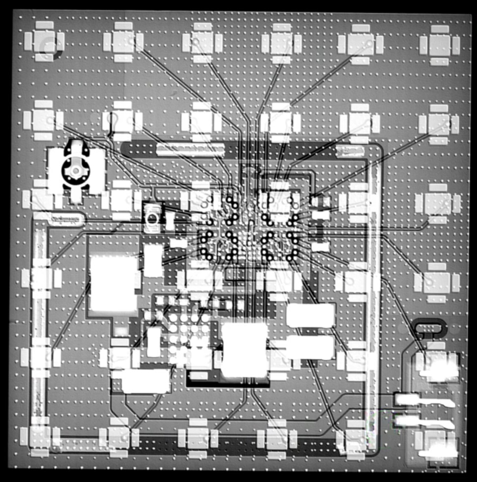
 For this project, [Henrik] shrunk the SAR set down small enough for a low-cost drone to carry. The build log is long and richly detailed and could serve as a design guide for practical radar construction. Component selection was critical, since [Henrik] wanted to use low-cost, easily available parts wherever possible. Still, there are some pretty fancy parts here, with a Zynq 7020 FPGA and a boatload of memory on the digital side of the custom PCB, and a host of specialized parts on the RF side.
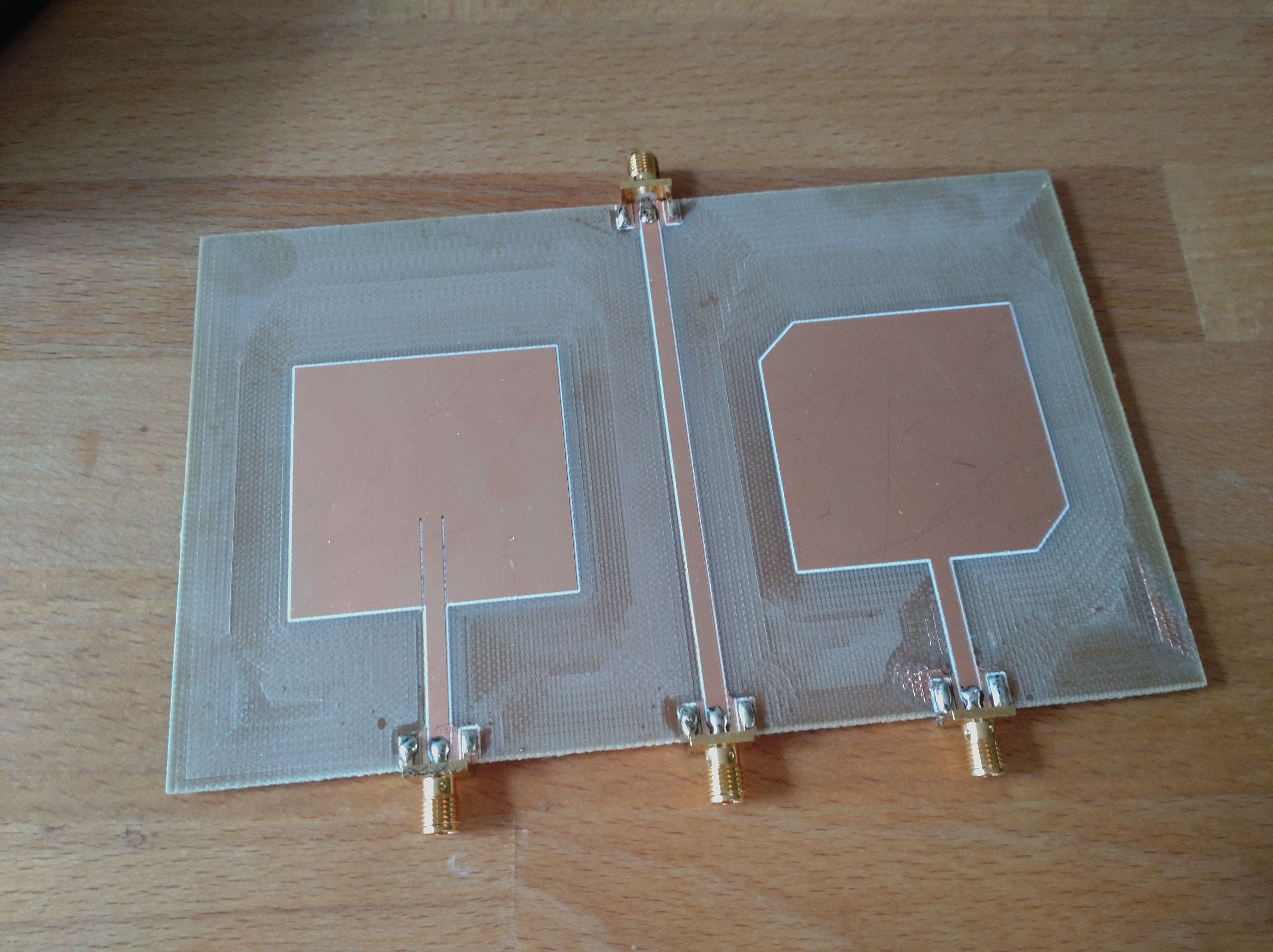
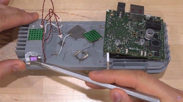
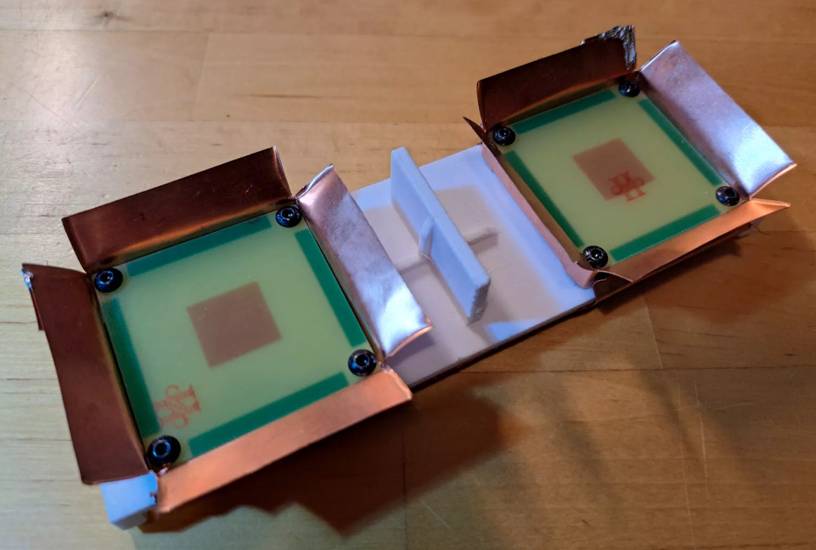
The antennas are pretty cool, too; they’re stacked patch antennas made from standard FR4 PCBs, with barn-door feed horns fashioned from copper sheeting and slots positioned 90 to each other to provide switched horizontal and vertical polarization on both the receive and transmit sides. There are also a ton of details about how the radar set is integrated into the flight controller of the drone, as well as an interesting discussion on the autofocusing algorithm used to make up for the less-than-perfect positional accuracy of the system.
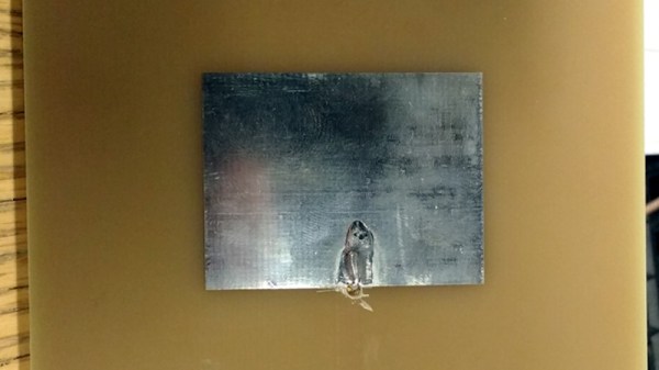
The resulting images are remarkably detailed, and almost appear to be visible light images thanks to the obvious shadows cast by large objects like trees and buildings. We’re especially taken by mapping all combinations of transmit and receive polarizations into a single RGB image; the result is ethereal.