Augmented reality saw a huge boom a few years ago, where an image of the real world has some virtual element layer displayed on top of it. To get this effect to work, however, you don’t need a suite of software and smart devices. [elad] was able to augment a microscope with the output from an oscilloscope, allowing him to see waveforms while working on small printed circuit boards with the microscope.
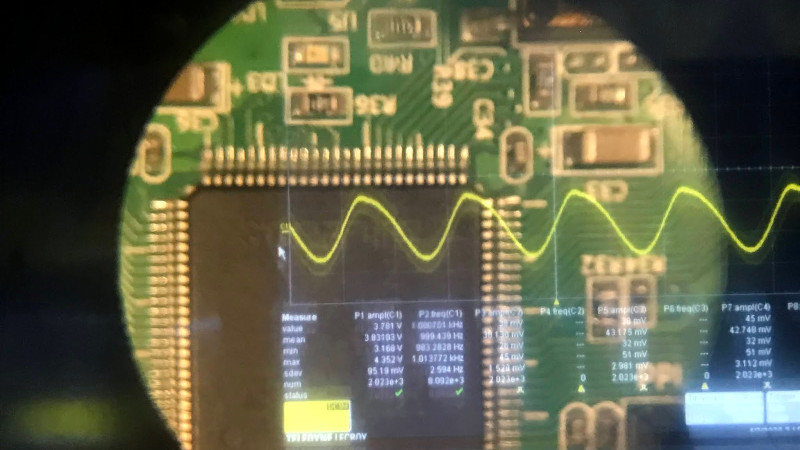
The build relies on a simplified version of the Pepper’s Ghost illusion. This works by separating two images with a semi-transparent material such as glass, placed at an angle. When looking through the material, the two images appear to blend together. [elad] was able to build a box that attaches to the microscope with a projection of the oscilloscope image augmented on the view of the microscope.
This looks like it would be incredibly useful for PCBs, especially when dealing with small SMD components. The project is split across two entries, the second of which is here. In one demonstration the oscilloscope image is replaced with a visual of a computer monitor, so it could be used for a lot more applications than just the oscilloscope, too. There aren’t a lot of details on the project page though, but with an understanding of Pepper’s Ghost this should be easily repeatable. If you need more examples, there are plenty of other builds that use this technique.


Nice idea, thanks for post :-)
Would be great to view a system with temp and other parameters on demand whilst viewing, just need method to determine where we are looking and maybe voice input to switch between data feed eg temp etc
There’s a device which can remotely probe a voltage, which is normally used for measuring thunderclouds. I forget the name, but it’s basically an electrode in a can with grounded shutters in front of it. When the shutters open, the electrode “sees” the charge behind the shutters. By cycling the shutters and measuring the resulting wave amplitude, you can probe the relative difference in voltage to a remote object.
If you had such a probe with a narrow aperture, you could connect it to the ground plane of the circuit and just point it at different traces to read their signals.
That would be a field mill, highlighted here just last week: https://hackaday.com/2020/04/03/oscilloscope-and-microscope-augmented-with-ghosts/
Overlay the circuit layout too, with net names, for even more awesomeness.
I red that first as pet names and thought you were working on Amigas, Budgie, Agnus, Denise etc…
Brilliant idea, and cool implementation
It’s not really *augmented* though, is it? At least not in the “AR” sense — the added display is not co-registering anything with the object in view, so you really don’t need to mix the images together.
So, why bother with all the complicated optics to combine the images? Most people have two functioning eyeballs, and the microscope usually uses only one. Use your unused eyeball to view a conveniently-placed display, and avoid degrading both images with a bad image combiner. If it’s a binocular ‘scope so much the better: use one tube for the additional display.
(Don’t say “but a stereo scope uses both eyes” — this mashup won’t work with a stereo scope.)
> this mashup won’t work with a stereo scope
Yes it would. If you duplicate the image to both eyes, you can select the depth plane where the display appears by the horizontal offset.
Yep, but that would be a different mashup…
I’d call it a HUD rather than AR
Yes, exactly that. Though I suppose in this context you could call it an HDD (head-down display).
The affordable stereo scopes close off one view – the left I think is standard – when you enable camera port. USB based O-scopes give you direct graphics on a PC. Combine them into one PC view without optical tricks?
I suppose dual cameras on the uscope and VR goggles where O-scope data is overlayed? I have all the gear but no time!
If you don’t need stereo why not combine the images digitally? That is a one-camera job.
For the internal reflection problem try a thin film first surface mirror. I bet a piece from an anti-static bag would do for an experiment.
This plus picoprojector.