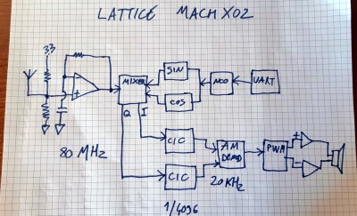
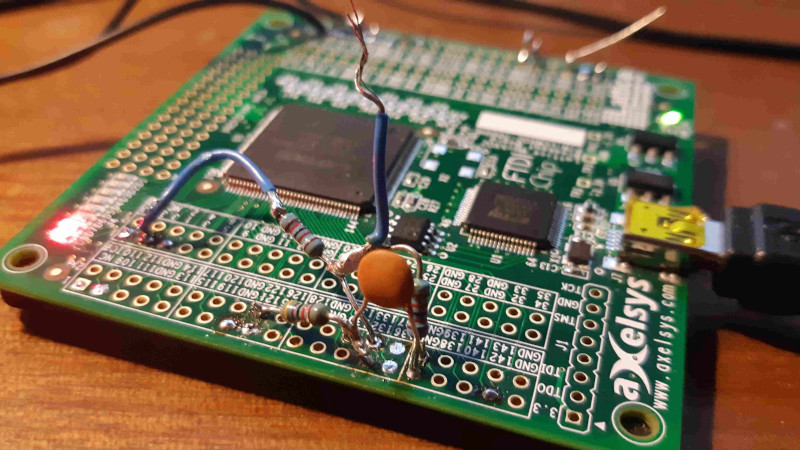
There was a time when making a radio receiver involved significant work, much winding of coils, and tricky alignment of circuitry. The advent of Software Defined Radio (SDR) has moved a lot of this into the domain of software, but there is of course another field in which a radio can be created via code. [Alberto Garlassi] has created a radio receiver for the AM and HF bands with a Lattice MachXO2 FPGA and minimal external components.
 He describes it as an SDR, which given that it’s created from Verilog, is a term that could be applied to it. But instead of using an SDR topology of ADC and digital signal processing, it implements a surprisingly traditional direct conversion receiver.
It has a quadrature AM demodulator which has a passing similarity to an SDR with I and Q phased signals, but that’s where the similarity ends. Frequency selection is via an oscillator controlled from a serial port, and there is even a PWM amplifier on board that can drive a speaker. The result can be seen in the video below, and as you can hear the direct conversion with quadrature demodulator approach makes for a very effective AM receiver.
If this is a little much but you still fancy a radio with minimal components, you should have a look at the Silicon Labs range of receiver chips.


Pretty clever :)
Jenny List said: “But instead of using an SDR topology of ADC and digital signal processing, it implements a surprisingly traditional direct conversion receiver.”
Nope, it is a DDC (Direct Down Conversion) receiver that DOES use an ADC and DSP. Right in the YouTube video’s comments it says: “An LVDS buffer of the Lattice MachXO2 is used as an ADC.” Plus, the post mixer quadrature filtering is done in two CIC (Cascaded Integrator-Comb) DSP filter blocks. While it it isn’t explicitly described, I have little doubt that the AM demodulator is also a DSP block. AM demodulation is simply the root-sum-squares of the I (In-Phase) and Q (Quadrature) signals following the CIC filters.
DDC fires a neuron, I think maybe it was the new hotness in digital proportional radio control in the mid 80s
One of the best hacks I’ve seen in a while. Teaches you the basics of RF and HDL at the same time!
How is the mixer implemented?
Author here. The mixer is quite easy. Input signal can be only +1 or -1, so it just changes the sign of the 12-bit local oscillator sin and cos signals. https://github.com/alberto-grl/1bitSDR/blob/master/Mixer.v
People talking about winding toroids like it’s a bad thing. I think they’re fun. And they look more complicated than they are, which makes people who see your work “ooh” and “ah” over magnet wire on a donut :P
People don’t like to work with their hands (or brains) these days. They want everything to be spoon-fed or automated.
Right? They just want to dl some libs and go, nothing more daunting than picking a few checkboxn. Oh wait, the UI minimalists took away all the check boxes!
Why are the RF parts always glossed over? The front end amplifier needs to not be an oscillator. The VCO must need to be very stable. Will any old junk work for the mixer? Or is it just that you can get all that stuff for $3 from ali-uknow?
So they learnt HDL and AM?
How is this not engaging your brain?!
SDRs are portrayed as both simple, and complicated.
For some, they are easy ways to an end, use that existing solution with that existing software, and look at all the things you can do.
Others see them as something mysterious and complicated, and avoid them, while buiilding the same sort of simple receiver that people have built for decades.
Way off in a corner are the people who understand what’s going on in SDRs (some of the issue is that they were rarely in the places where most hobbyists would learn about them, so they are seen as black box solutions to the two main groups) and build them as performance receivers. That group may include using toroids because they are looking for performance and understand good receiver design.
Coils are a major frustration when building anyone elses design, because either the premade coil or the particular core used turns out to be…
i) Plentiful in surplus… 10 years back.
ii) Found in a junk box that had been passed along among hams since 1920
iii) Product of an industrial specialist coil and core supplier that is actually still in business, but has a $50 minimum order and you have to submit an application to be allowed to have an account with them.
iv) Was in plentiful supply from Midsomer Worthy Radio and Apiary Supply Co last year, but the surplus they rebranded dried up.
v) Actually from Mouser, RS or other huge supplier … has been out of stock for months
I applaud the use of the FPGA itself as a delta sigma ADC.
I also admire the way the CIC filter gives an effective 6 bits more resolution.
I wish there were [cheaper] FPGA boards available with a good RF ADC (say over 100Ms/sec, 12-bit). Preferably with DSP blocks, which Alberto noted are missing from the MachX02 chip used here.
I built the LimeMicro 4 channel version VNA project, and yes it has everything you need except an output filter and PA.
LMS7002M (12bit 61.44MHz front end includes LNA on each phase lockable input pair)
Altera Cyclone IV EP4CE40F23
Practically, it is around a 55MHz rate limit only on the USB side of the FPGA, but I have not tried the PCIe version.
https://www.crowdsupply.com/lime-micro/limesdr
73
Yeah you can wrap a few coils of wire around it and have a radio too lol.
Back in my day we used the ZN414 as a single-IC radio :-)
https://en.m.wikipedia.org/wiki/ZN414
And http://members.iinet.net.au/~cool386/zn414/zn414.html
Article: “it implements a surprisingly traditional direct conversion receiver”
How’d you figure? it literally has a 20kHz digital IF frequency and an AM demodulator using quadrature samples. That’s a little more than a “traditional direct conversion receiver” does in my opinion!
IF is 0 Hz. I and Q are needed in the demodulator because the NCO is not locked to the carrier. If it were, amplitude of the I signal would be the audio output without any processing. But since there is a constantly changing phase shift, the output of the former approach would go from a maximum at 0 and pi, to complete silence for +- pi/2. The Q signal allows to overcome this by taking the root of the sum of the squares of I and Q.