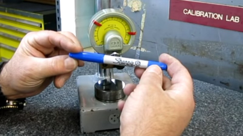
How we missed this one from a few years ago is unknown, but we’re glad to catch up with it now. Have you ever needed to measure how thick the ink in a Sharpie line is? Of course you haven’t. But if you needed to, how would you do it? Using a wicked-sensitive indicator gauge and levering an interesting test setup.
 [Tom] from [oxtoolco] got his hands on a tool that measures in 1/10,000,000th (that’s one ten-millionth) increments and was wondering what kind of shenanigans you can do with this Lamborghini of dial indicators. It’s one thing to say you’re going to measure ink, but coming up with the method is the leap. In this case it’s a gauge block — a piece of precision ground metal with precise dimensions and perfectly perpendicular faces. By zeroing the indicator on the block, then adding lines from the Sharpie and measuring again, you can deduce the thickness of the ink markings.
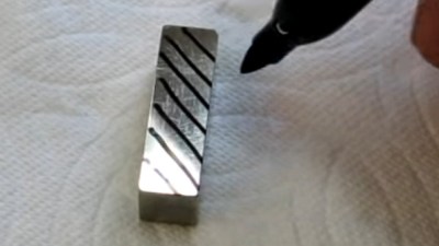
After arraying diagonal lines on the gauge block it is placed lines-down under the dial indicator. This distributes the ink layer across a larger area, as probing the ink line directly would likely result in inaccurate readings. On that topic the gauge block is moved using pliers, as introducing heat from your fingers could result in expansion of the metal upsetting the readings.
The results? Black, blue, and red Sharpie were all tested, alongside blue and black Dykem layout fluid. Ten samples of each were run and the readings were all very close, save a couple of obvious outliers. Clocking in the thinnest is black Sharpie at about 118 millionths of an inch (~30 microns) and blue Dykem was the thickest at 314 millionths (86 microns). [Tom] quips that since we now know the thickness, you could even use ink as a shim.
If you can’t get enough Sharpie in your life, try it as an extremely satisfying add-on for your plasma cutter.


I watched this video when it came out, but coincidentally, it was recommended again yesterday. I guess I wasn’t the only one.
I actually do use blue sharpie on the job for very fine work rather than blue layout fluid as a machinist.
It lays thinner for sure, and I know if I just remove it when cutting, its usually about 0.0001-0.0002″ max I’ll take off my part.
Watchmakers use sharpie for this very reason too.
Yeah you cut a surface layer cut of just 10mm and the paint is gone, that doesn’t mean you only took off 0.0001” use your brain fgs.
I know how to measure, thanks.
I work in sub 0.0001″ both as a machinist and watchmaker.
Of course I don’t actually use such a measure for direct measurements- that’s what indicating micrometers, indicating bore and air gauges are for.
That is a rough measure by eye to what I work by when I’m not measuring something critical.
Now get off my lawn.
using a water grider, no water on, to see how far down it has to go to remove the marker. .0001 is about what im seeing on my experiment. i cleaned the surface to near polish and then dried, marked raised the wheel and then slowly brought it down .00001 (according to the dro on the grinder) until the marker was removed. so ya 0.0001 is a good start
The trick is to put the blue sharpie mark on top of a black sharpie mark, then remove the blue without removing the black.
/s
Glad to see someone has a sense of humor that’s not condescending.
Yeah, I wonder if that could actually be done. Now that would be impressive.
Hey hey my my.
Out of the blue
and into the black
-Neil Young
I think you meant to say the gauge block has perfectly parallel faces, not perpendicular.
If the faces are perpendicular to the sides at all edges, the faces can only be parallel. It turns out that “perpendicular” in his sentence implies 3 pairs of parallel faces and edges that enclose angles of 90 degrees. On the other hand, a trapezoid has parallel faces with no guarantee of squareness. Which of those are gauge blocks though?
Both. And neither.
The manufacturing process starts with cutting and surface grinding all 6 faces. All faces will be flat and perpendicular to the limit of the grinding process, which for a machine making high precision measurement tools will be significantly better than those produced by the surface grinder in Uncle Joe’s Garage. +1 point for “Perpendicular”
However, that still doesn’t produce good gauge blocks. The two parallel measurement faces still need to be flatter than a surface grinder achieves for two reasons. First, for consistent measurements those faces need to lapped flat to remove local surface topography. Second, when two or more gauge blocks are stacked to create a custom length, the total length is increased by the gap between each block. When lapped, those blocks will wring together with a consistent gap of approximately 25um. (Each block is 25um undersized to account for that). Without wringing that gap is indeterminate). +1 point for “Trapezoid”
That is all true at 68F. The moment that the temperature deviates even 0.1F the block becomes convex (hotter) or concave (cooler) due to black body radiation, and you have “Neither”.
So I don’t really disagree with either characterization. The word I take issue with is “perfectly”. There is no perfection in the physical world.
This is a good summation of gauge blocks indeed.
Though, the 68 F (20 C) part can actually vary.
Some manufacturers/calibration procedures define 25 C as standard temperature for measurement tools. Others define 23 C….
The 25 C standard has some merit over the 20 C standard. Since most ambient environments are bellow 25 C, then one can always heat the calibration room to 25C without the need for fancy air conditioning. Heating being relatively trivial makes this a simple solution to ensuring that one actually can calibrate tools in most areas of the world.
Though, with the “modern” invention of air conditioning and how it has become fairly standard in practically all environments, we have the ability to cool a room to a temperature bellow what the weather outside happens to be, negating the whole issue.
Though, taking out our gauge block or indicator into the work floor that has another temperature would technically render its measurements to be off. (How much it is off should probably be specified in the measurement tool’s datasheet.)
Though, the work piece and tool will also have their own shrinking/expanding due to temperature variations….
Most of this thankfully isn’t majorly important for a lot of jobs. And the difference between 20 and 25 C isn’t much to quiver about when it comes to gauge blocks and indicators. Unlike some cutting tools that heat up to 100+ C throughout a single cut….
Thermal expansion is that one thing that will screw over projects with very strict dimensions if one doesn’t take it into consideration.
Does anyone else think that it probably has lines at (10) millionths [i.e. (1) hundred-thousandth] and not (1) ten-millionth?
I did a quick search online and found a pdf brochure for CEJ Mikrokators that says:
“The CE Johansson Mikrokator was introduced in 1938 and is still today the finest mechanical comparator in the world. A wide range of models are available, which gives graduations varying between .0001” (.005 mm) and .00002” (.0001 mm). The unique “Twisted Strip” principle on which all Mikrokators are based, provides many features which are not available on any other measure instrument.”
Ever since some youtube vid tried to convince me that a tenth is smaller then a thou I thanked my non exisistent gods (all of them) that I live in the metric part of the world.
A “tenth” is technically just a lazy deduction of “thousand” from “ten-thousandth”.
One can find similar shorthand used in both the metric and imperial ways of doing things.
Like some engineers working with metric stuff not specifying the prefix, since it is understood that they mean milli-meters. (Not specifying a prefix is fairly rude, and can cause confusion. Though, most people doing this doesn’t even specify that they are talking about a length either. Not to mention that it could just as well be inches or thou. (And yes, not all people using the imperial system specify units either….))
We almost never use tenths of an inch (0.1”). It’s usually either a multiple of one of the fractions (i.e. 1/8th, 1/16th, 1/32nd…) or it is in thousandths [0.100” = (100) thousandths].
So, when someone refers to a tenth, it is almost universally construed to mean (1) ten-thousandth (0.0001”).
About the only imperial ruler I have is in 10ths.
It’s mildly useful for counting / measuring the amount of holes on veroboard.
“Omitting units” here in Europe is not just some random shortcut. Length measurements in the whole engineering community are standardized on mm, from pretty small things to the size of bridges and buildings. Only for very small things we go to micrometer or smaller if needed.
But usually it’s not “omitted”. It’s just hidden in some small lettering in the title block, or even by specifying some norm according to which the drawing is made.
I used to have a wooden one that I must have not tried very hard not to lose. Had both sides in inches, 10ths on one edge annnnnd 12ths on the other… gah… well it did have the last half inch marked in 8ths/16ths on one side.
Don’t blame the system. An idiot can still say that 0.9 is smaller than 0.099, because obviously 9 is smaller than 99.
I heard him say it has, “ten (millionths) of an inch increments”, not, “one (ten-millionths) of an inch increments”. That matches what you can read later on the scale close-up, and also his math.
That PDF is… bizarre.
.0001″ is 2.54um, not 5um. I suspect that sentence was supposed to read. “between 0.0001″ and 0.00002″ (imperial), or 0.005mm and 0.0001mm (metric).”, and just poorly-worded. Of course, that would still be wrong, as the ranges extend to 0.000002″ and 0.00001mm respectively.
I’d trust Tom Lipton over some random PDF anyway.
I’m calling into question this author’s interpretation of what the guy says in the video, not what the guy says in the first 30 seconds of the video.
I understood it as (10) millionths, but the author purports that he is claiming (1) ten-millionth.
are we sure about these numbers? That would make black sharpie about as thick as the copper layer on an average PCB, and you *can* see the thickness of that from the side.
pcb’s copper thickness was my first impression as well, you need to compare something new to something you already know
His unit conversion is off. 120 millionths is just over 3 micron
30um sounds unrealistically thick
Does anyone else think that it probably has lines at (10) millionths [i.e. (1) hundred-thousandth] and not (1) ten-millionth?
I did a quick search online and found a pdf brochure for CEJ Mikrokators that says:
“The CE Johansson Mikrokator was introduced in 1938 and is still today the finest mechanical comparator in the world. A wide range of models are available, which gives graduations varying between .0001” (.005 mm) and .00002” (.0001 mm). The unique “Twisted Strip” principle on which all Mikrokators are based, provides many features which are not available on any other measure instrument.”
Further, if that is a grade 0 gauge block, the tolerance on distance between the measuring surfaces should be something like 0.000006” [(6) millionths].
If it’s not grade 0, then the tolerances are even wider.
Last thing, someone else mentioned thermal expansion above.
I did a quick calculation:
Using steel thermal expansion, 12E-6, and a gauge block size of 0.100”, a temperature change of 0.15F will cause dimensional changes on he order of (1) ten-millionth.
The (1) ten-millionth measurement capability in the articl is not correct.
Or wait, was the thermal expansion comment on the reddit page discussing this video?
I believe there is an error with units convertion. 118/1000000 inches are 2.99um not ~30um. Am I right?