Sharpie Mount Brings Some Color To Your 3D Prints

The average cost of a desktop 3D printer has dropped like a stone over the last few years. They went from a piece of equipment you had to wait your turn to use at the hackerspace to something you can pick up on Prime Day, which has definitely been a good thing for our community. But to get the price down, these printers are almost exclusively running single extruder setups with no provision for multi-material printing other than swapping the filament manually.

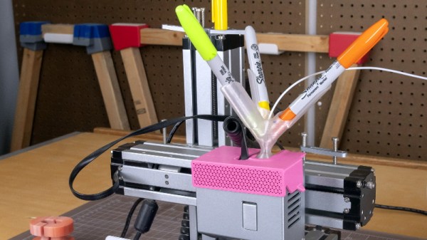
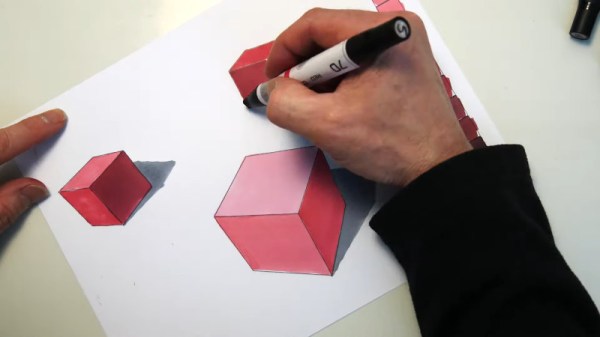
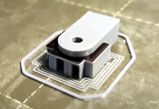
From a practical standpoint, that’s not much of a problem. But wanting to add a little visual flair to his prints, [Devin Montes] came up with a simple 3D printed mount that holds the tip of up to three Sharpie permanent markers against the filament as it enters the top of the extruder. When used with white or translucent filaments, these markers can give the final print an interesting splash of color. Obviously it’s not true multi-color 3D printing, but it can certainly make for some attractive decorative objects.

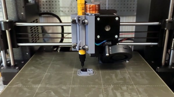
The mount is designed for the Snapmaker 3-in-1 3D printer, which is relatively well suited to such a contraption as it has a direct drive extruder and there’s plenty of clearance for the markers to stick up. The concept could certainly be adapted to other printers, but it might be a little trickier in the case of a Bowden extruder or an i3 clone that has frame components running over the top. It sounds like [Devin] is working on a generic version of the marker holder that can work on other printers, so it should be interesting to see how he addresses these issues.

Technically this isn’t a new concept, as makers were pulling off similar tricks back in the earliest days of desktop 3D printing. But this is an especially well-implemented version of the idea, and if [Devin] can really come up with a mount that will work on a wider array of hardware, we could certainly see it becoming a popular way to make printed projects a bit more exciting.

Making Custom Gradient Markers At Home

When doing high-end industrial illustration work, smooth gradients add a lot of production value to the final product. However, markers designed to do this well can be difficult to lay your hands on. [Eric] decided to create his own set of custom gradient markers, using commonly available supplies.

Starting with some existing markers that have dried out, the fabric ink reservoir inside is removed. A new one is created using tampons wrapped in heat-shrink, to replicate the construction of the original. Alcohol-based ink is required for smooth gradients, and [Eric] suggests using a heat gun to harvest the ink from a ballpoint pen, if store-bought is not available. The ink is then mixed with denatured alcohol to dilute it and injected into the fabric reservoir using a syringe. Each marker gets a slightly different ink mix to hit a range of lightness values for making smooth gradients.

It’s a tidy way of creating your own gradient markers in whatever color you may find useful. As a plus, the materials to do so are cheap and easy to obtain. We could even imagine 3D-printed marker bodies being an option, though nibs might prove a touch more difficult. We’ve seen [Eric]’s work before too, like this well-illustrated guide to using cardboard in product design. Video after the break.

Continue reading “Making Custom Gradient Markers At Home”

Improving 3D Printed Supports With A Marker

Anyone who’s spent some quality time with a desktop 3D printer is familiar with the concept of supports. If you’re working with a complex model that has overhanging features, printing a “scaffolding” of support material around it is often required. Unfortunately, supports can be a pain to remove and often leave marks on the finished print that need to be addressed.

Looking to improve the situation, [Tumblebeer] has come up with a very unique modification to the traditional approach that we think is certainly worthy of closer examination. It doesn’t remove the need for support material, but it does make it much easier to remove. The method is cheap, relatively simple to implement, and doesn’t require multiple extruders or filament switching as is the case with something like water-soluble supports.

The trick is to use a permanent marker as a release agent between the top of the support and the area of the print it’s actually touching. The coating of marker prevents the two surfaces from fusing, while still providing the physical support necessary to keep the model from sagging or collapsing.

To test this concept, [Tumblebeer] has outfitted a Prusa i3 MK3S with a solenoid actuated marker holder that hangs off the side of the extruder assembly. The coil is driven from the GPIO pins of a Raspberry Pi running OctoPrint, and is engaged by a custom command in the G-code file. It keeps the marker out of the way during normal printing, and lowers it when its time to lay down the interface coating.

[Tumblebeer] says there’s still a bit of hand-coding involved in this method, and that some automated G-code scripts or a custom slicer plugin could streamline the process considerably. We’re very interested in seeing further community development of this concept, as it seems to hold considerable promise. Having a marker strapped to the side of the extruder might seem complex, but it’s nothing compared to switching out filaments on the fly.

Continue reading “Improving 3D Printed Supports With A Marker”

Measuring Sharpie Thickness… The Ink Itself, Not The Pen!

How we missed this one from a few years ago is unknown, but we’re glad to catch up with it now. Have you ever needed to measure how thick the ink in a Sharpie line is? Of course you haven’t. But if you needed to, how would you do it? Using a wicked-sensitive indicator gauge and levering an interesting test setup.

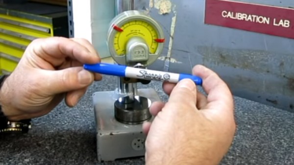
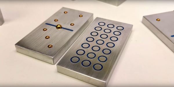
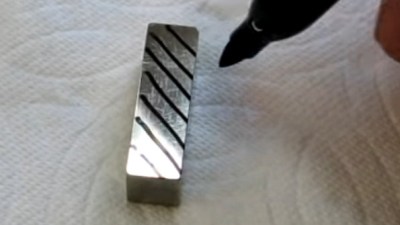
[Tom] from [oxtoolco] got his hands on a tool that measures in 1/10,000,000th (that’s one ten-millionth) increments and was wondering what kind of shenanigans you can do with this Lamborghini of dial indicators. It’s one thing to say you’re going to measure ink, but coming up with the method is the leap. In this case it’s a gauge block — a piece of precision ground metal with precise dimensions and perfectly perpendicular faces. By zeroing the indicator on the block, then adding lines from the Sharpie and measuring again, you can deduce the thickness of the ink markings.

After arraying diagonal lines on the gauge block it is placed lines-down under the dial indicator. This distributes the ink layer across a larger area, as probing the ink line directly would likely result in inaccurate readings. On that topic the gauge block is moved using pliers, as introducing heat from your fingers could result in expansion of the metal upsetting the readings.

The results? Black, blue, and red Sharpie were all tested, alongside blue and black Dykem layout fluid. Ten samples of each were run and the readings were all very close, save a couple of obvious outliers. Clocking in the thinnest is black Sharpie at about 118 millionths of an inch (~30 microns) and blue Dykem was the thickest at 314 millionths (86 microns). [Tom] quips that since we now know the thickness, you could even use ink as a shim.

If you can’t get enough Sharpie in your life, try it as an extremely satisfying add-on for your plasma cutter.

Continue reading “Measuring Sharpie Thickness… The Ink Itself, Not The Pen!”

Making Metal Dominoes

Nearly as versatile as a deck of playing cards, dominoes are a great addition to any rainy-day repertoire of game sets. [Apollo] from the Youtube channel [carbide3d] has manufactured for themselves a custom set of domino tiles replete with brass pips.

Cutting the bar stock to the appropriate size, [Apollo] ran a few test engravings and hole sizes for the brass pips. That done, all they had to do was repeat the engraving and milling process another couple dozen times, as well as all the requisite wet and dry sanding, and buffing. [Apollo] opted to use paint marker to add a little extra style to the tiles, and advises any other makers who want to do the same to set their engraving depth to .01″ so  the paint marker won’t be rubbed off when buffing the pieces.

When it came to installing the brass balls, [Apollo] undersized the holes by .001″-.002″ for a snug press fit — adding that the hole depth is a little greater than half the ball’s diameter. They used 1/8″ balls for the pips, and 3/16 balls for the center of the tiles which also allows the tiles to be spun for a bit of fidgeting fun during play. Check out the build video after the break.

Continue reading “Making Metal Dominoes”

What You See Is What You (Laser) Cut

WYSIWYG editors revolutionized content management systems, will WYSIWYC interfaces do the same for laser cutters? Unlikely, but we still appreciate the concepts shown here. Chalkaat uses computer vision to trace lines drawn in ink with the cutting power of a laser.

At its core, you simply draw on your work piece with a colored marker and the camera system will ensure the laser traces this line exactly. There is even a proof of concept here for different behavior based on different line color, and the technique is not limited to white paper but can also identify and cut printed materials.

This is a spin on [Anirudh’s] first version which used computer vision with a projector to create a virtual interface for a laser cutter. This time around we can think of a few different uses for this. The obvious is the ability for anyone to use a laser cutter by drawing their designs by hand. Imagine introducing grade-school children to this type of technology by having them draw paper puppets and scenery in advance and have it cut in shop class for use in art projects.

A red arrow indicates cut line, but a pink arrow is used for indicating positioning on a work piece. The example shows a design from a cellphone etched next to a positioning marker. But we could see this used to position expensive things (like a Macbook) for etching. We also think the red marker could be used to make slight adjustments to cut pieces by scribing a work piece with the marker and having the laser cut it away.

This concept is a product of [Nitesh Kadyan] and [Anirudh Sharma] at the Fluid Interfaces group at the MIT Media Lab and is something we could see being built into future laser cutter models. What do you think?

Continue reading “What You See Is What You (Laser) Cut”

Draw Your Own Vinyl Beats


The Dyskograf lets you make music with a magic marker. The musical installation looks much like a turntable for playing vinyl records. But instead of a spiraling groove containing the sounds, this uses marks on a paper disk to play sound samples.

You can see the light outline of several tracks on the paper disc shown above. By adding black marks the optical input of the Dyskograf knows when to start and end each sound. This is best illustrated in the video demonstration after the break.

The marker-based setup makes a lot of sense, and we think it would be perfect if the disc was a dry-erase board. It certainly makes it a lot easier to lay down new beats than this other optical turntable which required holes to be drilled in a vinyl record to play the sounds. While we’re on the topic you may also find this coin-based turntable sequencer of interest.

Continue reading “Draw Your Own Vinyl Beats”