
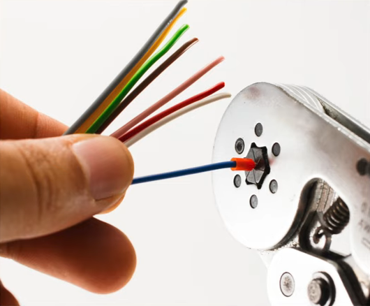
We think it’s pretty safe to assume that most of the electrical connections our readers are making out there involve solder or solder paste. But we’ve all made a crimp connection or two in our lifetimes. Maybe you’ve squeezed a butt connector here and there, or made an Ethernet cable. Beyond getting the wiring order right in the Ethernet cable, how much did you wonder about what was happening inside the connector?
 It may seem like solder is the superior option for making a low-resistance electrical connection. After all, you’re welding metals together with another metal. And this is usually all fine and good for circuit boards with sedentary indoor lives. But if a joint needs to be mechanically stable and survive in potentially harsh environments, you don’t want an alloy holding things together. You want metal to metal contact, and crimping is where it’s at.
A well-made crimp should last for several decades, but as Shelley Green explained in her talk at the 2019 Hackaday Superconference, good quality crimps don’t happen by accident. Good crimps are meticulously designed, and carefully executed from start to finish.
Crimping Dynamics
Shelley compares failed crimps to the O-ring disaster that plagued the Space Shuttle Challenger. Things like O-rings and crimp connections may seem small and inconsequential, but a failure to pay attention to their physical properties can mean catastrophe.
So what goes into making a good crimp? It’s all a matter of physics. The point of crimping is to make a connection with the lowest possible resistance. A permanent mechanical crimp involves forcing conductors together so that electricity can flow from A to B. Macro-structurally, good crimps occur when the connector is deformed past the yield point of the metal, and there is uniform deformation of the wires.
As Shelley explains, this bulk deformation is not the reason for low resistance, but the residual stresses between the conductors and the connector are responsible for keeping the system together.
If you look at the micro-structure of a crimp connection under a scanning electron microscope, the surfaces are quite rough, and there are only a few spots that actually make contact with each other. The high-profile places where contact actually occurs — called asperity spots or a-spots in materials science — are the real indicators of resistance rating.
The design of a good crimp has many aspects. First, you have to think about the application, the environment the crimp will live in, and the desired outcome of the crimp. Then come the implementation details — the crimp style, the wire, the terminals, and everyone’s favorite, the tooling. The fatter the cable gets, the more important all of these things become.
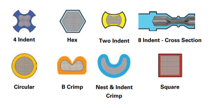
Shelley also discusses the merits of various crimp styles for different applications and environments, citing that the shape of the indenter can mean big differences in durability.
The Truth is in the Testing
In closing, Shelley touches on the testing schemes commonly used for crimped connections. As you might expect, the testing is designed to answer the questions proposed back at the crimp drawing board. Is the crimp low-resistance? This is verified with millivolt drop testing while the connection is under load. Will the connection prove to be mechanically robust? Time to hit the power tensile machine to test conductor breakage and pullout.
If you really want to judge a crimp, take a cross-section and examine it under a scanning electron microscope. Ideally, the conductors have formed a honeycomb of wedged hexagons. Any visible voids indicate air pockets, and these will add to the debilitating and inescapable microfilms already present in the wires.
There’s a lot more to crimped connections than you might have thought, and Shelley’s talk is sure to bulk-deform your neurons around the basics.


Hey, how come I don’t see the “mash it flat in a few different places with the hilariously blunt side cutter on the cheapo pliers because you can’t find the crimp tool” option?
That’s the B crimp or the “nest and indent” crimp depending on how good you are laying the screwdriver in the jaws with the connector to get the “indent”. Maybe the “2 indent?”
I’m about 179 nested interrupted tasks deep, maybe I was using them on task 13, I have no idea…
my adhd would like a word
You are my people
There are numerous brands that make nultifunction long nose pliers that have a special notch for crimping. Unless you also loose long nose pliers than I hope that at least you are not one of those “one screwdriver to fit them all” guy.
I always wonder why all multitools “designed for electricians” have complicated wirestripper but never a crimper? Once you have a good knife you can strip a wire but to crimp you need a dedicated tool. Hey Leatherman – I know you can’t hear me.
You don’t need ONE dedicated tool, you need around two drawers full (at least, where I work). Every manufacturer has a different crimp tool for each connector (sometimes a different one for the male and female pins). And they’re NOT cheap! I think our most expensive one was around $1k for a Japanese manufacturer.
Most of them are in the $300 range.
But a good crimp is better than a solder connection, because it doesn’t stiffen the wire. The wire will break before the crimp will let go, if it’s a solid crimp.
A good list of connectors and crimping tools: http://tech.mattmillman.com/info/crimpconnectors/
For the very common crimp lugs (fork, ring, bullet, splice, blade, etc) with red, blue or yellow sleeves, used with terminal strips, it’s helpful to be consistent with brands and tools. I’ve also found that even the knockoff controlled-cycle (ratcheting) crimpers do a decent job if you put in some time to set them up for the lugs you’re using.
Is there a different edit of this talk that allows us to see all slides and all of each slide?
Unfortunately there is not. We made several attempts to get a copy of the slide deck to edit it into the talk but there wasn’t one available.
This would have been nicer to look at if the camera was a bit more zoomed in and actually cover more of the slid instead of a large part of audience.
This link is pretty good for crimping:
http://tech.mattmillman.com/info/crimpconnectors/#minipv
These are also relatively interesting:
https://www.youtube.com/watch?v=foFgl8c17so
https://www.youtube.com/watch?v=bAO9eCS65jw
Thanks for that link. Awesome info!
Excellent talk, thank you Shelley
So then you’re saying that we shouldn’t tin the wires, then crimp them, and then solder that?
(Just kidding. But, really . . . I have to deal with this stuff all the time.)
For years I crimped DuPont connectors with needle nose pliers and pretty much avoided using any other form of crimp.
I’m ashamed to say, sometimes I even soldered them.
I also used tinned wire ends with screw terminals.
And frequently soldered wires directly to PCBs.
I tinned wires so much I was considering buying or building a solder pot.
Then I bought a cheap Dupont connector crimping tool.
For several more years I crimped DuPont connectors with needle nose pliers and pretty much avoided using any other form of crimp.
There is an official DuPont crimping tool which I’m sure is worth it for a professional that works with DuPoint connectors all day long but even a worn out old one needing service still costs hundreds of dollars.
Then I volunteered to fix work on something that was full of JST connectors. I bought a ratcheting crimper from Amazon made by a company called IWISS that does JST, DuPoint plus a couple other kinds of connectors that I don’t know anything about. I don’t remember the price but I’m sure it was less than $50.
This thing is Amazing! Why did I wait so long?!?!
Now I have a drawer full of crimpers for different kinds of connectors and wire sizes. I no longer believe that solder belongs anywhere near a stranded wire unless that wire is a jumper going from point to point on a PCB with no possibility of movement.
If the assembly will be potted you can also solder the wires to the board in my experience. Even in high vibration environments there are no failures. The potting of course prevents movement.
IDCs are also quite useful for quick mounting of cables on PCBs: https://www.mouser.be/datasheet/2/40/AVX-9177-500-1108384.pdf
This is especially good for field installation where the user may not have the correct crimping tool handy, or know how to use it.