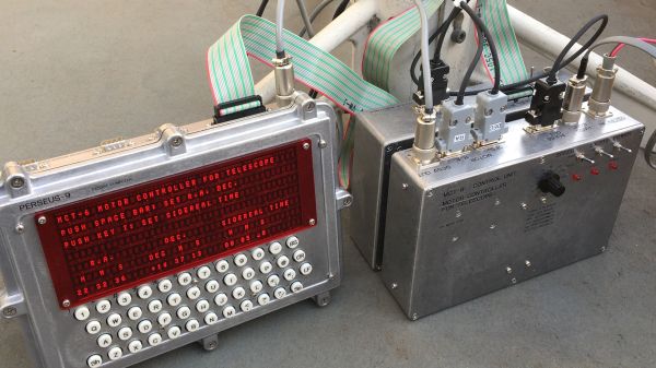
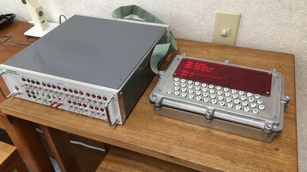
For certain situations, older hardware is preferred or even needed to accomplish a task. This is common in industrial applications where old machinery might not be supported by modern hardware or software. Even in these situations though, we have the benefit of modern technology and the Internet to get these systems up and running again. [Old Computers Sucked] is not only building a mid-90s system to receive NOAA satellite imagery, he’s doing it only with tools and equipment available to someone from this era.
Of course the first step here is to set up a computer and the relevant software that an amateur radio operator would have had access to in 1994. [Old Computers Sucked] already had the computer, so he turned to JV-FAX for software. This tool can decode the APT encoding used by some NOAA satellites without immediately filling his 2 MB hard drive, so with that out of the way he starts on building the radio.
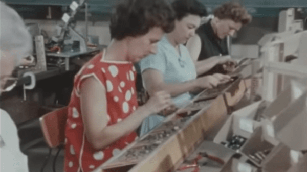
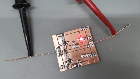
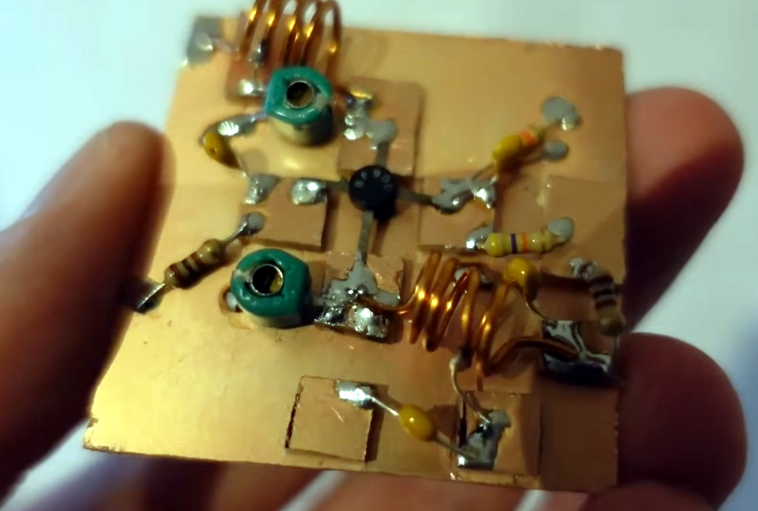 In the 90s, wire wrapping was common for prototyping so he builds a hardware digitizer interface using this method, which will be used to help the computer interface with the radio. [Old Computers Sucked] is rolling his own hardware here as well, based on a Motorola MC3362 VHF FM chip and a phase-locked loop (PLL), although this time on a PCB since RF doesn’t behave nicely with wire wrap. The PCB design is also done with software from the 90s, in this case Protel which is known today as Altium Designer.
In the end, [Old Computers Sucked] was able to receive portions of imagery from weather satellites still using the analog FM signals from days of yore, but there are a few problems with his build that are keeping him from seeing perfectly clear imagery. He’s not exactly sure what’s wrong but he suspects its with the hardware digitizer as it was behaving erratically earlier in the build. We admire his dedication to the time period, though, down to almost every detail of the build. It reminds us of [saveitforparts]’s effort to get an 80s satellite internet experience a little while back.
Continue reading “Receiving Radio Signals From Space Like It’s 1994”