We’re not exactly sure what kind of shenanigans [Conrad Brindle] gets himself into, but apparently it often requires cylindrical couplings to attach 3D printed parts to each other. He found himself designing and redesigning this type of connector so often that he decided to just make a parametric version of it that could be scaled to whatever dimensions are necessary for that particular application.
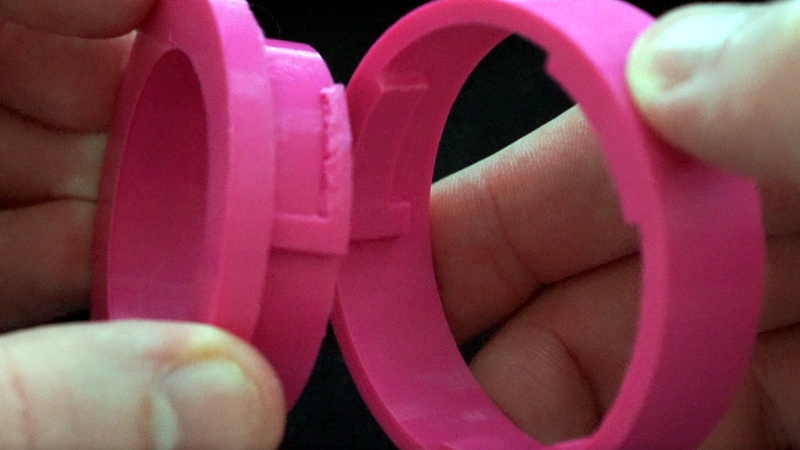
In the video after the break, [Concrad] explains the concept behind the coupler and how he designed it. Put simply, the tabs inside of the coupler are designed to grab onto each other once the coupler is spun. When he demonstrates the action, you can see that both sides of the coupler are pulled together tightly with a satisfying little snap, but then can be easily removed just by rotating them back in the opposite direction.
The nature of desktop 3D printing means that the female side of the connection requires support when printing, and depending on your printer, that might mean a relatively rough mating surface. [Conrad] notes that you’ll need to experiment a bit to find how small your particular machine can print out the design before things get too gummed up.
We can see how this would be useful for some applications, but if you need a printed joint that can handle a decent amount of torque before giving up the ghost, you might want to look into (mis)using one half of a spider coupling.


Nice! I’d say this is a nice implementation of a bajonet coupling. A little CA glue and it is permanent. Too bad this design is heavily dependent on good layer bonding, but for non-industrial purpose it looks like a neat. way to couple 2 parts temporarily. I wonder how many times you can couple.decouple this before it wears out. (ABS/PLA/PETG/nylon)
i don’t think i’ve ever used support, and i do a lot of little overhangs like that. if i can’t tolerate bevelling (a slanted bottom), then what i do is crenelations on the bottom of it. the radial movements sag a lot less than unsupported concentric circles.
makes a crappy surface about like the one he’s got. but i only print in one kind of PLA so i don’t know how the rest of the FDM world works.
Yeah, I agree, this is asolutely printable without supports. Just need to add bevels or a slant on the non-action side of the hooking parts and print it with those facing down.
Your right, It definitely can be printed with no supports, but for the seconds it takes to include them it does me no harm, especially when the rest of the print will probably need them once the coupling is implemented, quicker to have them then it is to set up support blockers.
Well, it’s not revolutionnary, it’s just a casual Storz-like fitting, the same used by fire soldiers for their lay flat hoses around the world for decades, what should be interesting in this case ? The fact that it’s tough fittings despite it’s 3D printed ? So what ? Is it so wonderful to find 3D printed rock-solid stuff ?
“parametric version of it that could be scaled to whatever dimensions are necessary”
not revolutionary, just useful if you find yourself needing one.
It’s not revolutionary, it’s mentioned because [Conrad Brindle] provided parametric script for making those connectors and every printing hacker likes parametric scripts especially for widely used (like you said) connectors.
Having a bad day?
It is wonderful, to find a good working solution, with parametric setup. Not every mechanical solution is a good solution to be 3D printed.
Like every manufacturing process, some things are more easy and favorably for the process, and others aren’t.
A design which tolerates the tolerances FOR the designed manufacturing tool, is a good design.
You don’t seem terribly interesting either, and yet here you are.
I designed this for table legs quick disconnect. Specifically for a hinged table that’s mounted to a wall, This way I have 2 table legs that can quickly disassemble.
I made a similar one for joining PVC water pipes weeks ago, but i’ve place a hole for a screw on the side that cross both parts once locked, so once it’s on lock position the screw ran through both parts preventing them from unlocking accidentally.
Here’s the video
https://youtu.be/VHFhZ90ZLMs
If I made a standard parametric design I’d want it to be right-handed (clockwise to attach) like every standard bayonet attachment, otherwise it would drive me nuts every time I tried to use it!
Just mirror it in the slicer.
Honestly, I never even thought about it, but that would be my immense frustration at not knowing if its tight or the wrong direction! I’ll fix it when I finish my current project (famous last words right??)
hmm. with gaskets, I could see this as a makeshift (gerry-rigged) bayonet connector for filters for my facemask..
Alright, I’ve put some updated pictures of the coupling being used in the build page. There’s also a video here: https://youtu.be/K4qwx6MicEI of it in use. Thanks for the feedback, it’s not so much the usual thing posted but saves the next person some time if they want the same thing!
I did something very similar. But it is made for laser cutting the single layers and then gluing the both parts together. And yes, it feels really satisfying to open and close.
But as this here it is missing some spring loaded tabs that makes it click together to prevent it from just rotating open on its own. May be some day…
Thank you for putting it this way: When the coupler is rotated, the tabs inside are intended to grip one another. My mother claims that her Layflat Hose Coupling is improperly sized for the apparatus. I’ll advise her to obtain a Layflat Hose Coupling so they can grip each other at once.