One of the major limitations of 3D printers is the size of the printable area. The robotic arm holding the printer head can only print where it can reach, after all. Some methods of reducing this constraint have been tried before, largely focusing on either larger printers or printer heads that are mobile in some way. Another approach to increasing the size of prints beyond the confined space typical of most consumer-grade 3D printers is to create some sort of joinery into the prints themselves so that larger things can be created. [Cal Bryant] is developing this jigsaw-based method which has allowed him to produce some truly massive prints.
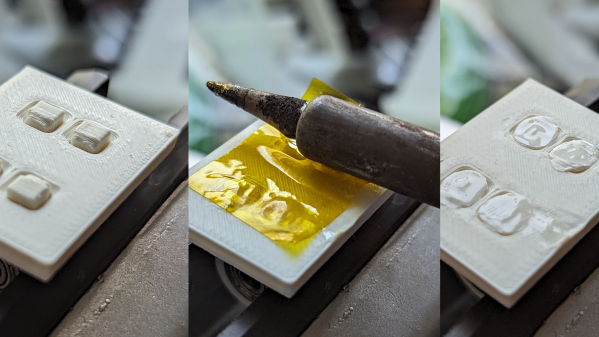
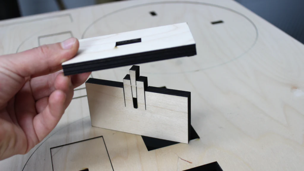
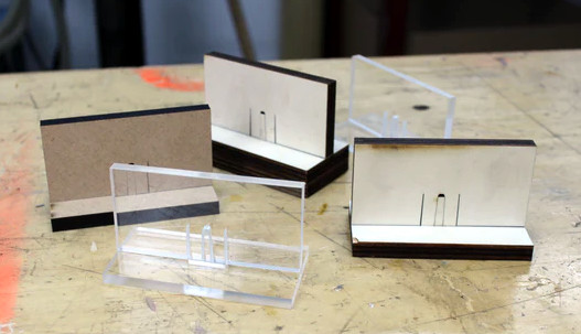
Rather than making the joints by hand, [Cal]’s software will cut up a model into a certain number of parts when given the volume constraints of a specific 3D printer so it can not only easily print the parts, but also automatically add the jigsaw-like dovetail joints to each of the sections of the print. There were a few things that needed prototyping to get exactly right like the tolerance between each of the “teeth” of the joint, which [Cal] settled on 0.2 mm which allows for a strong glued joint, and there are were some software artifacts to take care of as well like overhanging sections of teeth around the edges of prints. But with those edge cases taken care of he has some working automation software that can print arbitrarily large objects.
[Cal] has used this to build a few speaker enclosures, replacing older MDF designs with 3D printed ones. He’s also built a full-size arcade cabinet which he points out was an excellent way to use up leftover filament. Another clever way we’ve seen of producing prints larger than the 3D printer is to remove the print bed entirely. This robotic 3D printer can move itself to a location and then print directly on its environment.