Take This Cylindrical Coupler Design For A Spin

We’re not exactly sure what kind of shenanigans [Conrad Brindle] gets himself into, but apparently it often requires cylindrical couplings to attach 3D printed parts to each other. He found himself designing and redesigning this type of connector so often that he decided to just make a parametric version of it that could be scaled to whatever dimensions are necessary for that particular application.

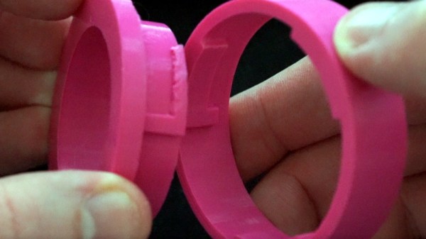
In the video after the break, [Concrad] explains the concept behind the coupler and how he designed it. Put simply, the tabs inside of the coupler are designed to grab onto each other once the coupler is spun. When he demonstrates the action, you can see that both sides of the coupler are pulled together tightly with a satisfying little snap, but then can be easily removed just by rotating them back in the opposite direction.

The nature of desktop 3D printing means that the female side of the connection requires support when printing, and depending on your printer, that might mean a relatively rough mating surface. [Conrad] notes that you’ll need to experiment a bit to find how small your particular machine can print out the design before things get too gummed up.

We can see how this would be useful for some applications, but if you need a printed joint that can handle a decent amount of torque before giving up the ghost, you might want to look into (mis)using one half of a spider coupling.

Continue reading “Take This Cylindrical Coupler Design For A Spin”

A Radar Module Teardown And Measuring Fan Speed The Hard Way

If you have even the slightest interest in microwave electronics and radar, you’re in for a treat. The Signal Path is back with another video, and this one covers the internals of a simple 24-GHz radar module along with some experiments that we found fascinating.

The radar module that [Shahriar] works with in the video below is a CDM324 that can be picked up for a couple of bucks from the usual sources. As such it contains a lot of lessons in value engineering and designing to a price point, and the teardown reveals that it contains but a single active device. [Shahriar] walks us through the layout of the circuit, pointing out such fascinating bits as capacitors with no dielectric, butterfly stubs acting as bias tees, and a rat-race coupler that’s used as a mixer. The flip side of the PCB has two arrays of beam-forming patch antennas, one for transmit and one for receive. After a few simple tests to show that the center frequency of the module is highly variable, he does a neat test using gimbals made of servos to sweep the signal across azimuth and elevation while pointing at a receiving horn antenna. This shows the asymmetrical nature of the beam-forming array. He finishes up by measuring the speed of a computer fan using the module, which has some interesting possibilities in data security as well as a few practical applications.

Even though [Shahriar]’s video tend to the longish side, he makes every second count by packing in a lot of material. He also makes complex topics very approachable, like what’s inside a million-dollar oscilloscope or diagnosing a wonky 14-GHz spectrum analyzer.

Continue reading “A Radar Module Teardown And Measuring Fan Speed The Hard Way”