If you own a radio transmitter, from a $10 Baofeng handheld to a $1000 fancy all-band transceiver, setting the frequency is simply a case of dialing in where you want to go. A phase-locked-loop frequency synthesizer or a software-defined radio will generate your frequency, and away you go. There was a time though when synthesizers were impossibly complex and radio amateurs were faced with a simple choice. Use an LC oscillator and put up with drifting in frequency, or use a crystal oscillator, and be restricted to only the frequencies of the crystals you had. [Mark Erdle, AE2EA] modified a 1950s broadcast AM broadcast transmitter for the 1.8MHz amateur band, and his friend [Andy Flowers, K0SM] thought it needed its crystal back for originality rather than the external frequency source [Mark] had provided. He documents the process of modifying a crystal oven and moving a crystal frequency in the video below the break.
A crystal oven is a unit containing the crystal itself alongside a thermostatic heater, and in this one, the crystal was a 1970s-vintage hermetically sealed HC6 device. He modified the oven to take a socket for older FT243 crystals because the quartz element can easily be accessed. [Andy] picked a crystal as close as he could find below the required frequency. He then ground it down with very fine grit on a glass plate, reducing its mass and thus its resonant frequency. We’re taken through the process of getting it close to frequency, but sadly don’t see the etching that he uses for the very last stage. At the end of the video, we see a QSO on the transmitter itself, which is something of an oddity in an age when AM on amateur bands has been supplanted by other modes for decades.
If you’re curious about the transmitter there’s a video thread following its restoration, and if the guts of older radio gear interests you then take a look at this aircraft receiver lovingly brought back to life.


I seem to remember reading about this, possibly in an old RSGB manual, with the suggestion that if you ground too much off the crystal (thus making it resonate at too high a frequency) you could bring it back down by judicious application of a soft pencil lead to the surface.
But… the idea was to make it clean.
the amount of dirt, and movement of dirt over the surface will de-tune it.
Worse yet, that dirt piles up at the nodal points on the crystal, and that is bad news in an air gap. Best case is it eventually gums the air gap and impedes oscillation so that the crystal stops working. Worst case it creates a high point and you get brush discharge, which was common with the HV circuits. It takes time for material to migrate, but it’s a ticking time bomb in the long run.
Yeah, you can put graphite or solder on there to bend the crystal frequency down…until enough migrates to one place and you get brush discharge, lots of heat in one place, and a cracked crystal. If it goes on easy it comes off easy.
If you take some of these apart you will see stripes on the electrode where the standing (acoustic) waves were…sometimes with a dirty, cracked crystal inside.
surely decreasing its mass aught to increase its resonant frequency
If you make it thinner, you’ll make it less stiff faster than you’re removing mass. So you’ll decrease the resonant frequency. When you make it shorter, you’ll increase the resonant frequency because you’re making it (relatively) stiffer AND you’re decreasing the mass.
If you actually watch all of the video, he does indeed grind it thinner, and the resonant frequency does increase. It does depend on the “cut” of the crystal exactly what happens, and by how much.
A lot has been written in the past about this, and as is said in the video, it was common practice certainly among hams back in the day to do this.
I remember attempting it as a kid at school, but must have damaged the crystal I had, as we couldn’t get it to oscillate after grinding. Probably not clean enough, but that was over 50 years ago!
As for “stiffness”, remember these AT cut devices, as he said, vibrate in a longitudinal sheer mode, not flexing like a plucked bit of metal.
73
I stand corrected. Thanks for your explanation.
It would be interesting to design a smallish home brew lapper to reduce the manual work inaccuracies. I imagine that keeping the AT cut angle would be hard manually.
I think the wording got garbled.
Grind a crystal and the frequency goes up, so you start with a crystal below where you want it. And if you go to far, scribble on it with a pencil to lower the frequency, as someone mentioned.
But this is about incremental changes in frequency. Grind a crystal too much and it may stop oscillating, the home grinder can’t do an even enough job. And the pencil lowers the frequency even less before it causes problems, though at least then you can clean off the pencil marks. Once you grind the crystal, you can’t put it back.
All grinding at home is about lengthwise, I assume it’s easier to do a proper job but there may be other factors.
Back when crystals for frequency control were a new thing, some actually did get some raw quartz and make their own. I’d seen mention of this but it was unclear, but a couple of months ago I did find a howto article from the thirties. I can’t remember the date or magazine.
Sure! Just pass me the file that adds material instead of shaving it away, and while you’re at it grab that pair of scissors that cuts things longer.
Very cool to watch. I’ve never seen the crystals modification done before and great comments in the video and above regarding the ways the resonance changes. Neat quick check apparatus (counter) also. I recently asked a question on Quora regarding how Pyotr Lebedew and J.C. Bose determined 50GHz and 60GHz frequency back in the late 1800’s would be neat having a video representation instead of pictures and diagrams of the range of methods. Amazing how cost effective the cheap micrometers are now days… I’ve been thinking about buying some to butcher for tuners. Thanks for sharing!
Etching can be done with ammonium bifluoride but its nasty stuff, it dissolves glasswork.
Frequency will go up because it removes material from all surfaces.
It turns out that the only frequency-determining dimension for thickness-shear mode vibration is the the thickness. F = k/t where k is a constant based on the crystaline axis and t is the thickness. Believe it or not, the absolute mass or volume of the crystal doesn’t factor into it.
The shape of the face doesn’t matter either, although approximately square or circular was used to avoid accidental coupling to other modes of vibration. I think rule of thumb was that the thickness should be much smaller (maybe 20x?) than the other dimensions, otherwise the crystal might start vibrating in the wrong mode when it gets excited.
This in not true for other modes of vibration where length and width at least partially if not wholly determine the frequency. This includes “tuning fork” watch crystals, and longitudinal or flexural modes (which vibrate more like bar on a xylophone). These are more common at LF. These more like the bar on a xylophone or a ruler vibrating with one end against a table.
>bifluoride
Yeesh. I’m not a big-time chemist, but I know enough to tell that this is one of those dark incantations. I assume you should keep it far, far away from sparks or flame or anything even resembling an oxidizer. Lest you erupt with that characteristic “FOOF!” sound. Fluorides frighten me.
There was a Retrotacular video about this a couple years ago.
https://hackaday.com/2015/03/03/retrotechtacular-crystals-go-to-war/
Matt Brunton has it correct. This was standard novice lore when you were limited to xtal control.
Back around 1980 I used a sheet of 600 grit silicon carbide sand paper and water on a glass plate to raise the frequency of a crystal. Takes a light touch and *very* few figure 8s, so check often. Water on the underside keeps the paper stuck down. And either pencil lead or a puff of clear acrylic spray to lower the frequency. Just be sure you mask off the electrical contacts if you use acrylic spray. The acrylic spray will shift the frequency a lot farther than pencil lead which is why I tried it. Worked great.
Those xtals were used in the only station I’ve ever had on the air. An Ameco 6L6 and rock on 40m and a Panasonic RF-2200 for the station receiver. I quickly learned not to try to adjust the receiver tuning during a QSO. The receiver performance was great, but it was not intended as a communications receiver. The antenna was an inverted V made with electrical blasting wire and a center insulator made from a piece of toothbrush handle. No balun at the feedpoint and 75 ohm coax. I was a very impoverished grad student.
Physical measurement is rather pointless. So I really don’t get the micrometer bit.
I still have my RF-2200. Great analog receiver for AM and FM, but pretty tough to tune SSB with the BFO.
I was actually referring to the following sentence from the post: “[Andy] picked a crystal as close as he could find below the required frequency. He then ground it down with very fine grit on a glass plate, reducing its mass and thus its resonant frequency.”
I admit I didn’t make what i meant very clear.
So back in the day crystals were in housings where the quartz was held in place with a contact spring with the understanding that the crystal would have to be ground and polished prior to use. Multi frequency selection was accomplished by switching a crystal from one of many in a bank of crystals even up through the early 1980s (although crystals by that time were hermetically sealed but still custom made to frequency). Major manufacturers were international crystal and sentry crystals and a few others in Oklahoma. I suspect that during the world war the reason for the concentration of crystal manufacturing in Oklahoma had to do with the Quartz Mountains near Altus.
Modern crystals are very different from the “grind your own” because they are carefully sliced in specific planes which provide controlled thermal/frequency stability. It was very common in the 1950s and 1960s for hams to buy boxes of surplus military crystals (which were almost free) to grind.
A New Zealander named Angus Tait made a business of taking surplus military radios, regrinding the crystals to comms frequencies and putting them in police cars and fire trucks. Look how that turned out.
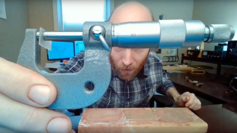
That’s not a crystal.
It’s a paving stone.
@ 03:55 There is only 250 Volts on what?
Is that directly over that paving stone?
No wonder they had to be that big and solid.
Thoroughly impressed by yester years technology.
Oh yeah. I have lots of very old electronics which aren’t impressive in many ways anymore–except durability and power handling. Sheer component mass is horrible for speed and cramming a lot of gates onto a tiny chip, but it sure handles an awful lot of heat dissipation and abuse.
It still works very well for audio electronics versus more modern innovations. We’ll never need anything faster than a couple dozen kilohertz in that field, since our ears aren’t getting upgrades any time soon. And contrary to popular belief, a good audio experience isn’t about fidelity or accuracy. It’s about power handling. The name of the game is to recreate that sound at live-concert levels without the nastiest kinds of distortion, crackling, clipping, rattling. Full stop. People love tube tone, and that’s the opposite of subtle fidelity. But big old tubes can pump a lot of power around when paired with transformers that weigh as much as a stack of cinder blocks. Or big fat power transistors attached to a heat sink that looks more like the fins on a motorcycle engine, if you wanna go a bit less retro. Power handling is the whole reason behind the idea that discrete components are preferable, and there’s a bit of truth to that if you interpret it correctly. All of that is the key to a nice amp, imho.
Note that it doesn’t necessarily mean deafening volume; there are subtle sounds that require a lot of power to manifest the same way you’d hear them in the flesh. But it’s good for deafening volume too :)
Why don’t you grind the length or width ? It would seem that is more easily controlled. If it doesn’t remain square, but one of the sides is sloped (‘right trapezoid’), does it change the Q ?
Neat video. I knew that the crystals were ground and tuned but I had never seen anybody do it before. Something to add to the bag of tricks.
This is black magic to me, really cool to see this level of work being done.
The only quartz oscillators I know are hermetically sealed in containers with 2 leads for 32,768 Hz vibration, for quartz timepieces.
It was always explained to me by watchmaking professors that after 7-10 years, the hermetic seal starts to go, letting air in slowly, changing this oscillation frequency, and the watch just starts to gain time in a way that trim pots can’t even fix.
At one time I was trained to do circuitry analysis on quartz circuitry for modern watches, with a Witcschi Q Test 9000.
How do these wafers hold a true accurate vibration frequency when they aren’t sealed in a noble gas canister?
All of this is fascinating, I’m not really an electrical guy, but I still get some of what’s going on since I know about the physics involved.
not really the hermetic seal causing crystal aging. no matter how well you grind the crystal you always leave tiny even molecular level imperfections that shed and increase the frequency. Proper crystal oscillator design puts a reactance with the crystal to put the oscillator on frequency. In the 80s when you ordered a crystal it typically had a 2 week delivery time for the inevitable drift from surface shedding to stabilize. The manufacturers would thermally cycle the crystals during this time. You could order 1 week or 2 day delivery but the crystals made this way we’re considered unstable junk because of the drift and uncertain future stability. There was all kind of science done to predict long term frequency drift with time. outcome is that most really old hermetically sealed crystals are pretty stable.
This might be entirely true, but it doesn’t jibe with what I was taught professionally, and to my knowledge, what is still taught in the remaining watchmaking schools in the US.
I mean this in seriousness- I’d love any resources you or others could point me to to shed light on this further for 32,768 hz oscillators in quartz watches.
The school I attended closed a couple years ago, and my professors were not electrical engineers- but there was a student who was one, a phd former electrical engineering professor, who became one for the program after I left. He never seemed to disagree with this assessment of failure mode, and this position was backed by international people of deeply knowledgeable means on technical issues, still is.
Not saying you’re making it up at all- but ypu have a different type of understanding on this, perhaps, that might be deeper in another area. Anything you can point towards that would refute my teaching and show another explanation?
Drew, you might be right. I’ll the first to admit that one of my major technology holes is inexpensive Chinese crystal resonators for watches. I know almost nothing about how they’re made, how they break etc. I’d follow the lead from your instructors. On the other hand, if we’re talking about precision communications crystals, different story. In the 80’s I was a design engineer that designed 1 temperature compensated crystal oscillator module (TCXO) and a handful of oven oscillators (OCXO). These were manufactured in multi hundred thousand quantities. These were (at the time) very high precision devices that had to meet stability of 1.5 parts per million over a temperature range of -30 to +50C and had to do this with a custom ground crystal cut to a subharmonic of the customer’s licensed frequency.. if you consider that the only parts we had were thermistors, resistors, diodes and voltage variable capacitors and these had to fit in a smaller box than a small tic tac box, I sometimes look back wonder how the heck *anyone* ever did it, At the time it was a standard technology product made by a bunch of competing manufacturers although none from one manufacturer would work in any of their competitor’s radios.
As far as references? Geeze Louise there are tons of textbooks about this.
If you’re not into (expensive) books and prefer a quick summary, maybe a Google search “at and sc cut crystal frequency stability aging” brings in a number of manufacturers description from companies like Bliley labs and Colorado Crystal. Also Wikipedia has a pretty good summary of it as well.
All of this stuff is obsolete because most of the high precision stability equipment is now synchronized with the GPS timing signals as a primary standard and digitally compensated oscillators as fallback.
The only thing you couldn’t compensate for was drift due to aging, so yeah we got pretty deep in this.
As I suspected- we may have been talking about two different types of crystals in their mountings.
I learned some things by asking the question though so this is not bad.
My primary interest is always how something relates directly to horology and in this case it would be the quartz canister oscillators in standard time pieces.
I’ve still never seen a very detailed scientific study on what causes the real failure but what I mentioned is what we were taught about that specific type of oscillator failure.
I learned more about crystal oscillators here than I’ve seen in years so all of this is good.