I’ve been told all my life about old-timey Army/Navy surplus stores where you could buy buckets of FT-243 crystals, radio gear, gas masks, and even a Jeep boxed-up in a big wooden crate. Sadly this is no longer the case. Today surplus stores only have contemporary Chinese-made boots, camping gear, and flashlights. They are bitterly disappointing except for one surplus store that I found while on vacation in the Adirondacks: Patriot of Lake George.
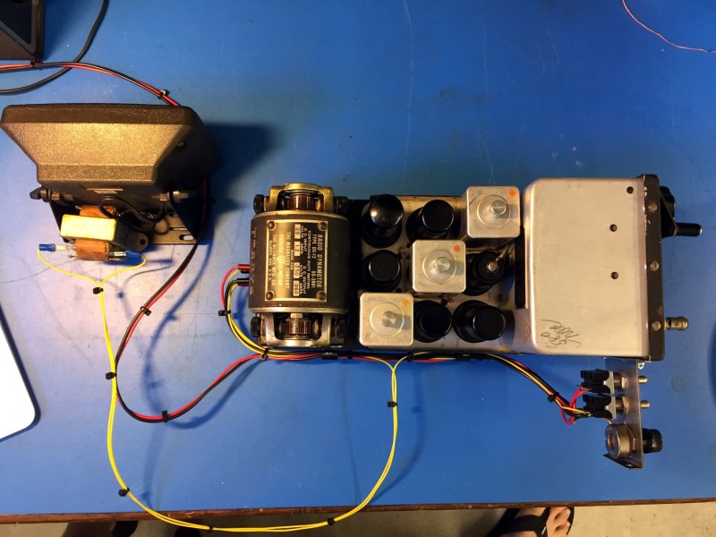
There I found a unicorn of historical significance; an un-modified-since-WW2 surplus CBY-46104 receiver with dynamotor. The date of manufacture was early-war, February 1942. This thing was preserved as good as the day it was removed from its F4F Hellcat. No ham has ever laid a soldering iron or a drill bit to it. Could this unit have seen some action in the south Pacific? Imagine the stories it could tell!
My unconventional restoration of this radio followed strict rules so as to minimize the evidence of repair both inside and out yet make this radio perform again as though it came fresh off the assembly line. Let’s see how I did.
A Flavor of Radio for Every Need
The list of radio systems installed into WW2 aircraft goes on and on, even more so for special aircraft like night fighters which depended entirely on radio navigation and radar systems to fly their missions and jamming aircraft who’s purpose was to hide fleets of bombing aircraft or invasions of coastal territories. There were different systems for each specialized task:
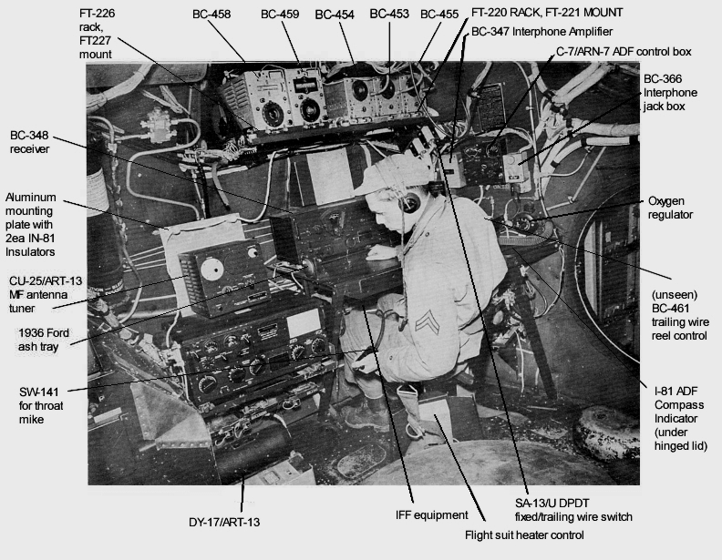
- Long range radio systems to communicate back to base, typically consisting of an ART-13 transmitter and a BC-348 receiver.
- Short-range radio systems designed for aircraft-to-aircraft communication, known as command sets subdivided into a multitude of bands.
- Air to ground radio communication equipment.
- Radar beacons to identify the aircraft as a friendly (identify friend or foe, or IFF).
- Radio navigation receivers of various types from
- radio direction finders,
- glide slope receivers for landing purposes, and
- TDOA radio navigation systems akin to modern GPS (except that you had to manually measure the time difference of arrival with an oscilloscope and line it up on special charts), such as GEE.
- Radar systems of various types.
- Electronic warfare receivers to detect enemy radar signals.
Part of the ARC-5 Radio Equipment
Somewhere in this menagerie of radio systems, you would find a CBY-46104 receiver. This receiver is part of a series of radio gear known as ARC-5 command sets, which describes an entire class of WW2 transmitting and receiving equipment for aircraft-to-aircraft communication. This class of equipment includes separate transmitters and receivers that can be controlled remotely by the pilots through a remote control head mounted somewhere in the flight deck.
These radios were designed in the mid 1930’s. Transmitters utilize a MOPA (Master Oscillator Power Amplifier) architecture supporting AM phone and CW (aka Morse code) transmission. Receivers use a single-conversion heterodyne architecture similar to that of big wood console radios of the era. Octal tubes were used as the active devices and the operational frequencies did not exceed 20 MHz, which was considered a high frequency for the mid 1930’s.
This radio gear was light-weight for WW2 standards, the CBY-46104 weighs only 6 lbs and is made entirely from aluminum. It is a carefully balanced chassis/radio design for weight minimization (these were installed in aircraft after all) while also remaining rugged and able to provide stable operation across MIL-SPEC temperature ranges and intense vibration.
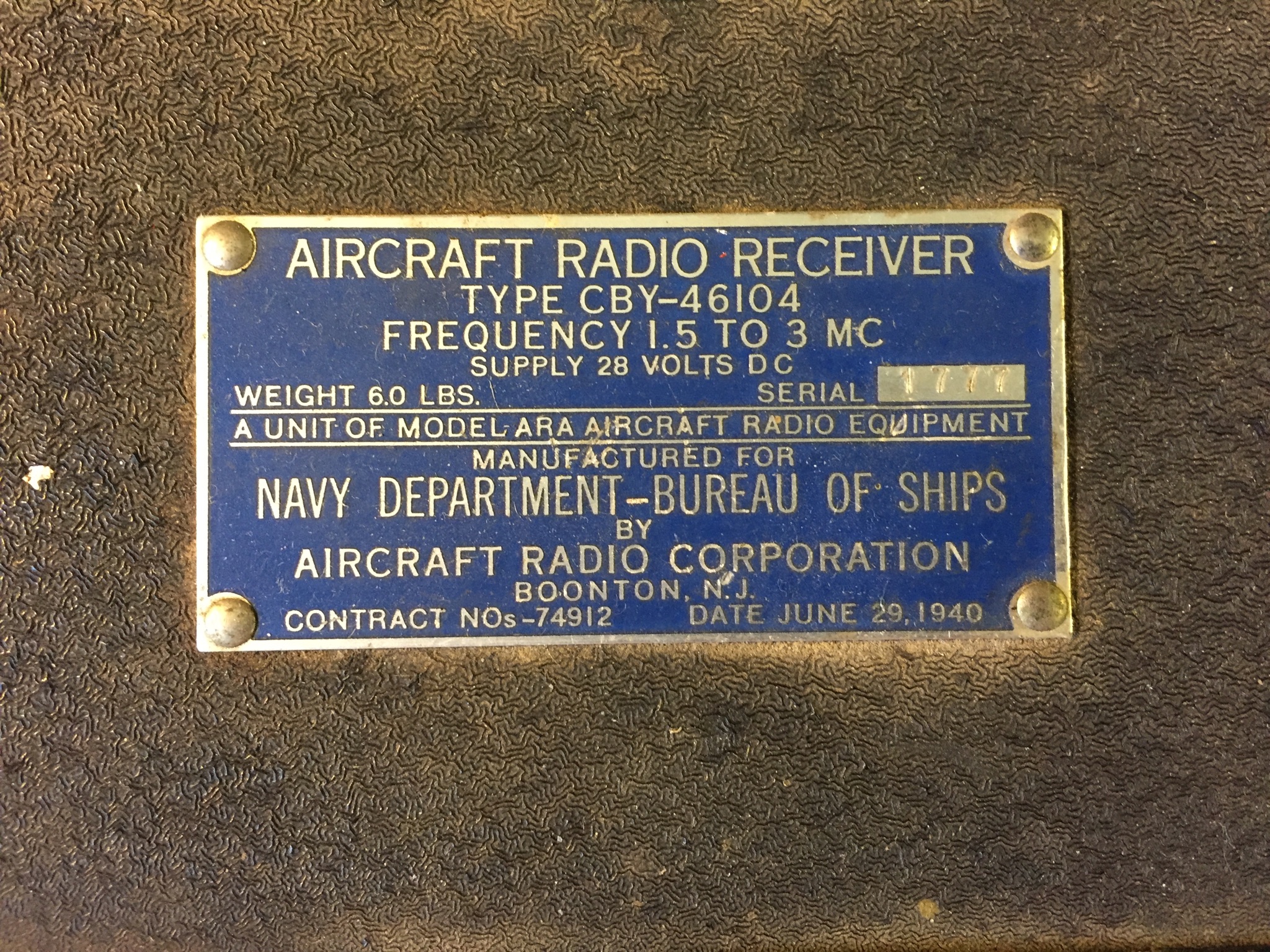
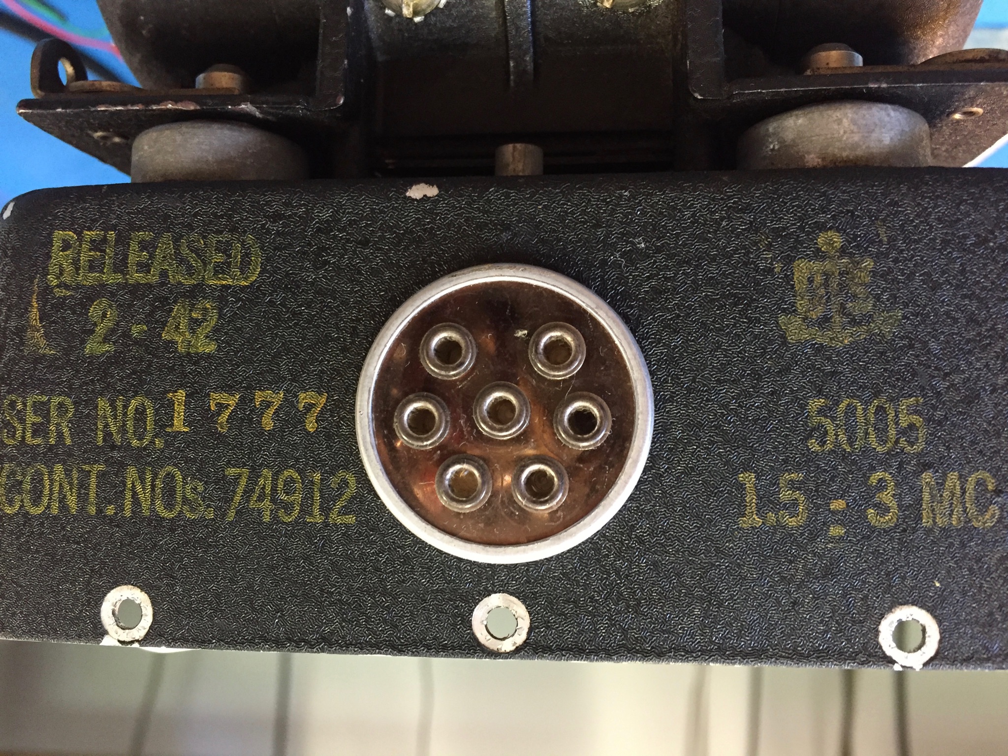
The CBY-46104 covers 1.5-3 Mc either AM or CW (it can also tune in SSB in CW mode), made by the Aircraft Radio Corporation of Boonton N.J. in February 1942 with SN# 1777. The contract for this run was #74812 dated June 29, 1940, demonstrating the ramp-up in war materiel purchasing/production in advance of Pearl Harbor. In other words, they were planning ahead for this conflict (an interesting book on this topic, how war production in the US was set up in advance by an executive from General Motors who established GM’s global supply chain in the 20’s and 30’s).
Rules of Engagement for the Restoration
To preserve this historic treasure my rules of restoration were:
- No replacement of any components whatsoever.
- If a capacitor failed, then it must be re-stuffed.
- Unit must be made fully operational to original specification.
- Unit must run off of its dynamotor, as it was intended.
- No holes can be drilled, either on the chassis or on the plug-in.
- Rear power connector must stay as-is.
- No chassis modifications whatsoever.
These were not easy rules to follow because, as we know, the first step to antique radio restoration is to replace all of the paper and electrolytic capacitors, saving a lot of headache and time.
Initial Assessment
Instead of replacing the caps I opted to do a cursory check of the caps and try powering the unit up for an assessment. I tested the electrolytic and paper caps with a Fluke DVM in resistance mode for obvious shorts or low impedance. All caps were open-circuit as far as my DVM was concerned (unfortunately DVM’s are not sensitive enough for a proper leakage test, more on this later).
Next I had to locate documentation. Fortunately, it is easy to find documentation for WW2 radio gear because it was ubiquitous in the late 40’s through the early 70’s in amateur radio stations across the world (here is a PDF link to the manual for all or most ARC-5 gear). A typical practice of the post-WW2 era was for the Elmer hams to gift an ARC-5 receiver to a young ham working to earn their license. With such a receiver the young ham would be able to tune in radio traffic from all over the world and practice listening to Morse code (CW) transmissions.
It is not easy hooking-up military surplus radios because they typically use multi-pin multi-use connectors for power and other controls. From the documentation I figured out what had to plug into the multi-pin connector on the back; +28 VDC, an external CW/AM toggle switch, RF gain control pot, 600 ohm speaker (I used an 8 ohm speaker and impedance matching transformer).
But one might ask, “with 28VDC input, how do we get high voltage for the vacuum tube plates?” Here is how they did it in WW2: This unit has what is known as a Dynamotor. High voltage was generated from the Dynamotor. Everything from receivers to transmitters that ran on low voltage DC busses used dynamotors to generate the 200-1000V, or more, needed for operation.


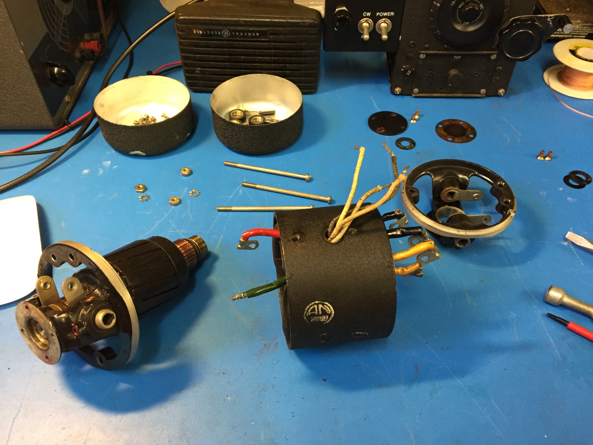
Dynamotors are motor-generators; in my case one end is a spinning motor at 28VDC motor and the other end is a 250VDC generator. Rather than having two motors with two shafts tied together (larger units on ships actually used such configurations) this motor is built into one compact unit with two armatures and two sets of brushes. 28VDC in, 250VDC out all the while spinning like a whirly-bird.
I removed the bells (end caps) from both sides of the motor. I applied 28V and, carefully with my finger, pushed the armature on the 28V side of the dynamotor to coax it into operation. It spun up like a 1950’s jet engine! Whrrrrrrrrrrr…..
After about 30 seconds the Whrrr sounded slightly bogged down, loaded down actually, by the vacuum tubes warming up and drawing current from the 250VDC output of the dynamotor. Then noise came out of the speaker. I hooked up my 20m dipole and to my amazement I was tuning in AM broadcast stations at around 1500 Kc. There was a lot of noise coming through the speaker likely due to failed decoupling caps that would otherwise quiet the dynamotor’s hum. The receiver was not too sensitive, and tuning was jammed up at the higher frequency ranges on the dial. It was at this point that I shut it down, this radio wanted to work and all I had to do now was clean her up and fix a few things.
Servicing Capacitors and Resistors
First order of business was to accurately test the capacitors because it was obvious that some were not functioning to spec. It is tough to test capacitors correctly, it requires multiple tests to troubleshoot for bad capacitors:
- Test with a DVM in ohm setting.
- Testing capacitors with a DVM in resistance mode will show which are short-circuited but it will not reveal the leaking capacitors that are only leaking ever so slightly (e.g. have extremely high DC impedance) at high voltages. DVM testing only reveals the short-circuited caps, this is a necessary first step.
- Test for specified value.
- A capacitor must operate to its specified value so it is good to test to see if the cap is functioning as a cap. This test will show if a cap is functioning as a cap and as specified. Unfortunately some leaky capacitors will measure to their specified value, so this test is not definitive.
- Electrostatic Resistance (ESR).
- In modern low-voltage electronics the key metric to capacitor goodness is ESR. This test will confirm that a capacitor is presenting a low impedance to a high frequency signal. In other words, how much series DC resistance does a capacitor present when it is measured at a relatively high frequency. Ideally, capacitors should present no resistance whatsoever, but practical capacitors do present some low resistance and bad capacitors present a lot more than some resistance.
- With that said, ESR testing is useful for testing the electrolytic power supply capacitors in tube equipment.
- Leakage.
- For high voltage capacitors, the key metric of goodness is leakage. How much current leaks through an old capacitor? If small amounts of current (on the order of single-digit uA) leak through then that capacitor is bad. A leaky cap will act like a high value resistor, in the many-multi-mega ohm range thereby reverse-biasing the grids of tubes or discharging itself causing it to not function like a capacitor at all. Leakage testing is absolutely critical and must be done for each and every cap.
Given all of that, the keys to troubleshooting tube equipment are to test the capacitance of each cap to verify that it is functioning and test the leakage to make sure it is not leaking current between circuits.
To check for value and leakage with one test device you must resurrect an old piece of test gear known as the capacitor checker. I found mine at the Dayton Hamvention many years ago for $10. It consists of a few dials and a very sensitive ‘Magic Eye’ tube which will deflect leakage is detected. Mr Carlson’s Lab has a great video on how to use one.
To check each cap I had to remove each of them from circuit, one at a time. There’s no getting around this, otherwise you might miss-read the cap value or leakage test. Remarkably enough, the vast majority of these Feb 1942 capacitors tested good. This is a testament to not replacing all the caps if you don’t have to. I found that all but three of the metal-can-sealed wax and paper caps (special to ARC-5 and other WW2 radio equipment, otherwise known as ‘flower pot’ capacitors due to the shape of their metal cans) and the electrolytic caps needed to be replaced. I opted to re-stuff the defective caps by opening the metal cans, extracting the guts, and putting in a modern replacement, then gluing the cans back together.
Resistor Care
Next I checked all of the resistors with my Fluke DVM. The nice thing about tube gear is that when the power is turned off the tubes present an open-circuit and therefore you can test resistors reliably in-circuit without removing them.
Old resistors tend to increase in value over time. Particularly the higher valued ones in the 100’s of K or M ohm range. For this radio not one resistor was out of tolerance! Amazing for resistors built before February of ’42.
Servicing the Dynamotor
I then moved onto cleaning the Dynamotor. It was running but not well. Fortunately these are easy to service, they are designed so that anyone with a flat-head screwdriver can fix them. I found a video on servicing a similar motor and proceeded to strip mine down, clean out the old grease in the bearings, put new grease into the bearings, clean the armatures, and re-assemble. Dynamotor worked perfectly, just like new again!
Problems with the Tuning Variable Capacitor
With good resistors, good caps, a working dynamotor I then moved onto the tuning mechanism. Something was not right with it, the plates on the large variable tuning cap were literally grinding against each other. I made the necessary repairs; it appears that this unit was dropped at some point and the fixed plates, which were normally electrically isolated from ground, had popped off of their plastic insulators. I put them back into place and the tuning unit was good as new.
Old radios are like old cars, they could use an alignment from time to time. Given the changes to the tuning unit I realized that I had to do a full alignment. I followed the instructions from the original service manual, aligning the IF first (using a modern synthesized signal generator to get it spot-on), then the front-end variable cap assembly that I had just repaired. The later was tricky, with some high, medium, and low-band-specific alignments required.
With the receiver aligned I tested its sensitivity. I measured <1 uV on AM at 2 MHz, more than good enough for me and easily exceeding the original factory spec.
Build a Wiring Harness


At this point I had two toggle switches and a pot with a mess of wire shoved into the rear panel connector pins. To organize this mess and to make a more permanent functional display for the radio I built up a small external switch panel and drilled a hole pattern in it so it would simply bolt to the side of the radio using two of the existing machine screws on the case. I left the original rear power plug in place and found out that ‘miniature banana’ plugs fit perfectly into the WW2 socketed pins. I used these banana plugs to connect up the control panel and a 600 ohms speaker. With all of this I made a neat wire harness to tie it all together.
Final Testing, It’s Alive!
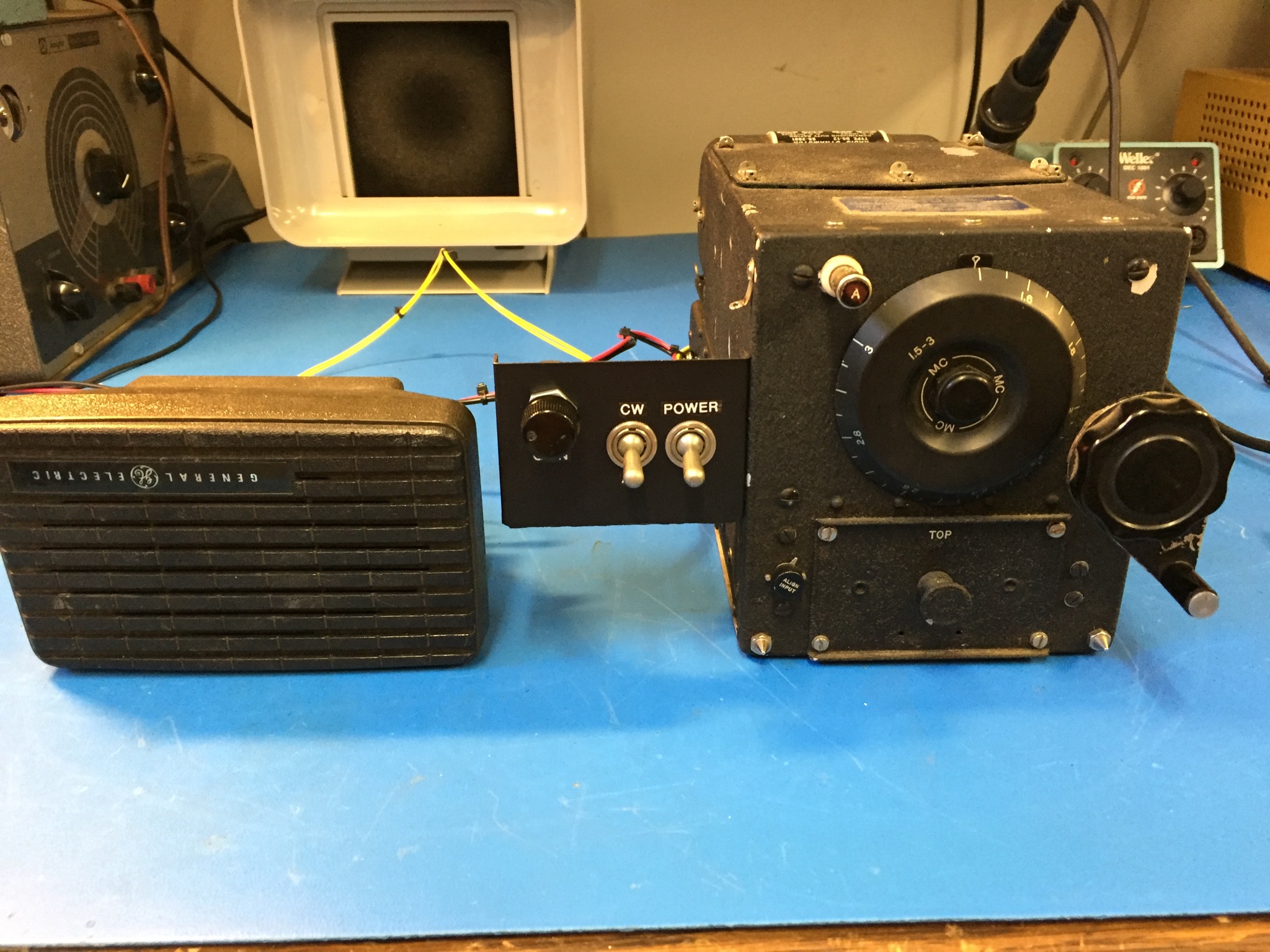
Now that everything was in order it was time to try the radio in its final configuration. I connected up my 20 m external dipole and powered up the radio. The whrrrr was smoother than ever. Within seconds stations starting coming in strong, much louder than before. I tweaked the antenna coupling control, they were louder still. I listened to a basketball game from an AM broadcast station in Chicago, I tuned into WWV at 2.5 MHz, and tuned in an 80 m AM net. What an incredible receiver, it was wide awake and operating to its original specifications once more!
After 3 Years of Operation…
This unit switches-on every time without fail, whrring away for innumerable demos for friends and family. Everyone is thrilled and amazed to see a dynamotor-powered receiver that is running almost entirely on its original parts and as it was originally built.
By accident I even connected the DC input backwards, reverse polarity. The dynamotor roared into life but the radio never produced audio. I figured out the problem after about five minutes of reverse polarity operation. Fortunately for me, and unlike solid state equipment, no damage was done. I re-connected it the correct way and it worked just as well as it did before.
If It’s from WW2, Don’t Hack it, Preserve It!
We are now at a point where the surplus WW2 electronics should no longer be hacked to bits. Join the movement, there are many others who restore WW2 and other vintage gear to be original as possible. Most of the community orbits around Electric Radio Magazine. Test those capacitors before throwing them in the garbage and keep those filaments lit!


Cool
Bravo!
(on the work you’ve done and the article)
So, I suppose in WWII it would have been “Baker!) but it probably didn’t make sense.
B^)
Great job! As much as I’ve read about Dynamotors, I’ve never seen on in action. SO glad that the seller didn’t touch it and you kept it as stock as possible! John in Texas
nice
Very cool! Those old caps still working is amazing, and a testament to just how terrible the knockoff electrolytic caps are.
Small world. Two weeks ago I was at the Communications Museum in Seattle, and they had a Command Set just like yours, tuned to the Boeing Tower frequency. Nice work on the restoration.
Isn’t “ESR” short for Equivalent Series Resistance? “Electrostatic” has nothing to do with it.
Eric Steven Raymond
Erythrocyte Sedimentation Rate
Yes, that was my first thought as well
There is nothing like powering up a dynamotor . Mine came out of a old sheriffs car. I think it’s output is 3k.
Nice! Finally someone restoring something instead of shoving in a raspberry pi.
You beat me to it. :)
The F4F was the Wildcat the F6F was the Hellcat. The radio could have been used in both. The F4F is often underrated today because it’s performance numbers look so bad on paper but it had a very good kill ratio and it was the main US fighter at Midway. The Hellcat was of course better but that is only to be expected.
Does anyone know: were the radio crystals of WWII military planes kept in a secure place, and only inserted into the plane before a mission? I know ATA ferry pilots had no radio, even on repaired planes, and was wondering how that was accomplished.
The Wildcat was completely outclassed by the Zero, which enjoyed a 12:1 kill ratio over American planes at the beginning of the war; with the exception that the Wildcat was amazingly durable. After Coral Sea it was immediately concluded that a Wildcat dog fighting a Zero was suicide. Through the use of coastal spotters, advanced radar and early warning, they were able to gain an advantage by gaining altitude and make high speed diving attacks shooting in a “high pass”. When they did not have enough time to gain altitude they had catastrophic losses. At Midway Wildcats, like Devastators, took very heavy losses. The Hellcat was superior to the Zero in every way except in a slow turn. But American pilots still avoided dog fighting and utilized the dominant characteristics of the Hellcat to inflict heavy losses. By the end of the war, the Hellcat had a 19:1 kill ratio over Japanese aircraft. This was helped by the increasingly short supply of qualified Japanese pilots as well as the Zero’s lack of performance compared to the Hellcat. American ingenuity in developing strategies that maximized the impact of their planes’ strengths and minimized the consequences of their weaknesses was a key factor in stopping Japanese expansion in 1941.
Now *that* is how you do a restoration! Very impressive! It drives me nuts to see someone take something that should be in a museum and butcher it. Your painstaking dedication to detail and historical accuracy means that the next caretaker of this radio will still have plenty of historical context surrounding each of the individual parts, construction, etc. Very, very well done!
Come on, there are a gazillion of those out there. And literally hundreds of them reside in museums. I’m totally on your side generally; but it’s really not a crime to play around with gear like that and drill some holes. There are plenty.
When we were young; in the 70s; we destroyed literally tons of stuff like that just for fun. Big dynamotors explode in total awesomeness if you apply mains voltage to them.
Of course I am not proud of that today…
There seemed to b warehouses full of them up into the 80s along with a lot of other WWII stuff still around. I don’t know if they finally all sold out, or everything just got sent for scrap when Soviet surplus and post Soviet cheap optics and gear filled out the surplus pages during the 90s.
The time station is WWV on 2.5 MHz exactly. That would be a good station to calibrate his dial on.
I was also surprised by the quality of the caps in my WS19. All paper/wax capacitors were fine.
The electrolyics, however, were extremely leaky and did not reform.
I opted to remove the dead electrolytics and keep the old parts in a little paper bag.
Yes, the rolled paper/wax seem to hold up forever unless electrically or physically abused. I don’t mess with a lot of old kit now, but when I was getting into it, if the paper/wax caps looked okay visually, not toasted, or the wax dripped out or anything, I’d usually give them a pass and move on, can’t recall they ever made me come back to them. I tend to have such a bad opinion of caps made since the mid 90s though, that I figure if I leave something in that seems marginal it still might last 5 years whereas a replacement might last 3. If run out of trim, I might do a little naughty and just strap a little booster cap across it. This wasn’t restoration though, it was trying to get the last few cents worth of service out of ancient crap for as little additional investment possible.
Oh BTW I think reforming is only a thing since ITT came out with the first thin foil caps, such that the conductive layer was thin enough to burn out around a short.
Derp, sorry only trawled the top layer of the grey matter there, been reading some vintage computer pages where they (mis)use reforming to mean blowing out the shorts, forgot the older process.
I was a bit surprised at how the caps actually tested. I’ve become a believer in testing all the caps now.
It’s a real shame it can’t communicate anymore because it uses megacycles. Today we use Mega Hertz which are totally incompatible.. just kidding. Excellent project. It’s definitely going the extra mile to do this and if you can keep it going a little longer than 20 years that will make it a hundred years old and possibly the future generations will see it as value and keep the restoration going.
But if you have an old frequency generator also marked in cps,
It could receive its output.
Great project! One minor nitpick from the writeup – F4F refers to a Wildcat, whereas a Hellcat uses the F6F designator. Which one was this radio used it? Or both?
I was one of the youngsters who got an ARC-5 receiver in the mid 50’s. I bought it from a fellow in a wheel chair who had a shed full of surplus electronics. He had built a little one tube power supply to replace the dynamotor. It tuned the 40 meter ham band, and I spent many an evening with it. It led to my career in electronics.
Sadly, it disappeared in one of my folks’ moves.
“Sadly, it disappeared in one of my folks’ moves.”
Did it occur to you, that is maybe why they moved as often as they did?
B^)
I lost some neat stuff the same way.
Looking back at my own history, it’s clear that the kids toys were always the last priority in a move.
I am familiar with these radios and have had a few of them in the past, but don’t have any now. I got good use of a BC-455, the one that covers 6.0 to 9.1 Mc. It had the rare 12 Volt dynamotor so I could use it as part of a mobile setup in the car. I also got a lot of use of the BC-453 low frequency version as an improvement to my Hallicrafters receiver connecting it to the 455 Kc IF to take advantage of the low IF (85 Kc) to give improved selectivity. Later, I built some crystal controlled converters and use the BC-453 as a tuneable IF. I never played with the transmitters very much. I did have a BC-348 at one time, when I was in college and that was my receiver for the station I took to school paired with a home made CW transmitter using a 6L6 on 80 and 40 meters. It’s a long story, but an abused ARC5 dynamotor adapted for use powering an autopilot got me an interesting gig on a sailing yacht back in the 60s. I agree with the sentiment about not hacking, but restoring these venerable veterans. 73 – K9LJB
That connector full of separate banana jacks is just screaming for a 3D printed jig to hold them all together.
Nice job on the restoration. A true restoration, not a “replace old carcass with modern guts” restoration like we’ve been so used to seeing. (Looking at you, [MisterM]!)
That’s a good suggestion and i’ve never thought of it before. Actually, the 3D printing would solve a nasty problem in making WW2 gear operate again; finding the connectors!
Nice! Found this today, while researching how to fix up my CCT-46192 (roughly like the AN/ARC-5 R23) that hasn’t seen power since probably 1985. Miraculously it came to life when powered. These things are built like tanks!
ahh jeez, that was meant at top level, idk how it ended up as a comment 3 levels down. sorry guys
Very nice job! de K7ZB
Very nice rebuild, a lot of patience to test each capacitor multiple ways. It was stated that an 80 m AM net was monitored but 80 meter band is outside of 1.5 to 3 MC. Maybe 160 meter AM net?
I noticed that too …
Those old radios are fun. I used to have a transceiver built in the U.S. for use in Russian tanks, during WWII. At one time (1976) I had it mounted in my ’65 Datsun (named Ziggy), and used to work CW on 40 meters with headphones on and a key strapped to my leg. Of course, it had a dynamotor power supply, which we used to (only half jokingly) refer to as a rotating short. I did make one modification to it: I added a pot to dial in some positive feedback around 2 of the IF stages. That increased both the gain and the selectivity of the radio. I wish I still had it, but the car it was in was stolen from me, and when I got the car back, the radio was no longer in it.
Nice restoration. Most likely I’m the odd person put on the topic. As long as they don’t affect my person, family, friends, or our property, I don’t care what others do with ‘their’ property. The only exception for me is that historical books and papers should be preserve, so we can know what has preceded us. For example In regards to this topic any service manual or schematics, hopefully that have been hopefully digitized along the way.
Yeah, I try to scan whatever manuals I can but I have yet to figure out how to scan the manual for my old military generator since it is bound. Most places cant scan books without destroying the original unless you pay a fortune
Macona:
I have a Book Scanner that can do bound books. Which Gen Set Manual do you have?
Drop me a note off line and I may be able to help with the scan.
I can do 36-inch wide scans and prints from a plotter if needed.
Chuck
N7UVZ
good on QRZ
It’s tedious, but even photographing each page with a digital camera is better than nothing. I did that once with a couple of books and used OCR software on the images to create a searchable PDF. The results were actually quite nice. Admittedly, OCR isn’t going to be useful for photos, diagrams, and symbols, but in most cases even raw camera images will be far more useful than not having the data at all.
It takes a lot
https://www.youtube.com/channel/UCYQXlaLJRzzW9TYSynzOAvg
ESR is Equivalent Series Resistance and NOT Electrostatic Resistance as you said.
Nice work. If only more kit of that vintage was restored and demonstrated, then some of the static aircraft exhibits would at least sound like they were still usable. (Even if it was just the dial lights in some!)
The museum ships often have fully operational radio rooms wherein folks make the old radio gear work again. There is a Museum ships radio contest once per year, ships will operate CW and AM with the old gear and plug in a modern transceiver to operate SSB.
Very nice restoration! I like old military shortwave radios. It’s just too bad that there’s not as much to listen to in HF these days, unless one jumps into amateur radio.
I think it’s laudable that he kept the mods and replacements to a minimum. I used to be all about modding things to unrecognizability but that was when new gear was so much more expensive. Now there are so many easily modifiable kits and open source designs the remaining historical items are better off as museum pieces.
Still though… I’m not sure about clinging on to old capacitors. If one fails and the failure results in burning up some much harder to replace part was it worth it? At least replacement capacitors can be hidden on the underside of the chassis. Besides if you really want the original experience.. it didn’t have 70 year old caps in it 70 years ago! It is probably more authentic after a good re-capping and re-alignment.
Cool project, and congratulations to this great device!
Just one thing about caps: ESR is not “Electrostatic Resistance”, it´s the “Equivalent Series Resistance”
Excellent posting and thanks for the dynamotor rebuild info.
I have a couple stock R-2x series receivers (navy version) and BC series (Army version).
I’m also in agreement to not drill holes or modify per the surplus conversion handbooks –
One exception – I removed the flower pot caps carefully with a soldering iron and dental pick/solder sucker to unwind the wires. I built capacitor packs that fit in the space and attached to the chassis with a solder lug. I kept the flower pots to reverse the mod.
For B+ I went to the dollar store and bought 20 9v batteries and snapped them together into a B+ “strip”
I use that although I have read on the ARC5 collector pages these radios will perform with voltages as
Low as 50v on the plates but diminished audio
I have one receiver with the dyno I run stock and the caps appear fine so I left them in. That radio has an acceptance stencil from Alameda Naval Air Station
73 Mike AA9IL
I was bemused by these “rules of engagement”:
1. No replacement of any components whatsoever.
2. If a capacitor failed, then it must be re-stuffed.
3. Unit must be made fully operational to original specification.
If I have to restuff a capacitor because its failed, in my book that means I am fitting a new component. So rule 1 fails immediately.
Yes, its good to get a radio operational to its original specification. The chances of doing that without replacing any components is probably around 1% for radios of this vintage – and I have done dozens of them over some 26 years. Most radios need every paper capacitor replacing, otherwise the leakage in them just destroys the resistor droppers, or blows up something else. Its very rare that resistors are all in tolerance (as here), but it could happen (German resistors are excellent in this regard). Most times a good proportion of resistors have to be replaced…..with modern parts, because if you find old parts of the same type they are all out of tolerance too.
Rule 3. is generally totally incompatible with rule 1. A compromise has to be made – you can either leave a radio totally original, OR you can have it working to its original specification. Not both. I don’t think you kept your own rules here because you replaced some capacitor with new parts.
I think you did a great restoration – just a pity about nonsensical rules!
Very cool job!
There is something I don’t get though:
“I found that all but three of the metal-can-sealed wax and paper caps (…) and the electrolytic caps needed to be replaced”
But before that you stated:
“Remarkably enough, the vast majority of these Feb 1942 capacitors tested good”.
If the vast majority tested good, why did you have to replace all but three capacitors?
Great write up. I have a 7mhz version of this receiver (black navy) that I used in my novice days in 1976. It needs some work too. The audio amp tube socket is a problem. Will have to replace it. But now with what you have done, I will go thru the receiver completely. It was a fine radio for use on cw. I made a lot of contacts on it. Unfortunately, I did modify the chassis to accommodate some kind of tuning knob and vernier in an attempt to slow down the tuning rate for cw. Not reversible. And I used an external home brew power supply and soldered directly to pins. It wont be factory original but will represent the era.
My elmer was a B17 radio op. So my unit has some historical meaning and context. He taught me all about the command rx and tx. I even used the receiver as a tunable IF in a science fair project experimenting with mixers/converter for 10mhz WWV. Took first prize in my category!
73, gary/NJ8BB
Awesome.
I love seeing the WWII equipment properly restored. But a question: why go to all of the work to restuff caps and things, all hidden deep inside, but then have all that modern bright plastic wire, tie-wraps, psychedelic banana plugs and a modern speak hanging on the outside, it’s kind of trashing it up, like someone painting graffiti on it? Just curious. And yes, I’ve restored many WWII radios, and the peanut gallery is always annoying.
I had about 25+ years ago picked up this old WW2 4 cyl generator a PU-35/U , remember it had about 8 hours on the hour meter, it might have about 9 when I got it I fired it up, had it outside in a box, would like to get rid of it if anyone would be interested, can send some pictures. One of the tag’s has Signal Corps U.S. Army , can e-mail me for phone #. L.I.N.Y.
Nicely done. I remember visiting a couple of friends (G4EYL and G8LUV) in the 80s, and they noticed some CBers on a ham band. One of them went under the stairs and there was the characteristic sound of a dynamotor spinning up… they blasted out Morse at (I think they said) 2kW for a few seconds and then G4EYL used her best local-radio announcer’s voice to tell them they weren’t welcome. End of problem.
ESR is an abbreviation for “Equivalent Series Resistance”, not “Electrostatic Series Resistance”. It is a measure of the effectiveness of a filter capacitor.
In my experience, the dynamotors were often the first thing to be discarded on those sets. I’m surprised.
I have a BC-348/Q5er (BC453 w/ front-end mods to tune to the 915 KHz I.F. of the 348) that my Dad used in the late 40s.
He also had a BC-459 that he used on 40 meters. Lots of good DX.
Cheers, W7PYX