Thanks to low-cost WiFi enabled microcontrollers such as the ESP8266 and ESP32, it’s never been a better time to roll your own smart home system. But that doesn’t mean it isn’t daunting for new players. If you’re looking for an easy first project, putting your old school doorbell on the Internet of Things is a great start, but even here there’s some debate about how to proceed.
Most people stumble when they get to the point where they have to connect their low-voltage microcontroller up to the relatively beefy transformer that drives a standard doorbell. We’ve seen a number of clever methods to make this connection safely, but this tip from [AnotherMaker] is probably the easiest and safest way you’re likely to come across.
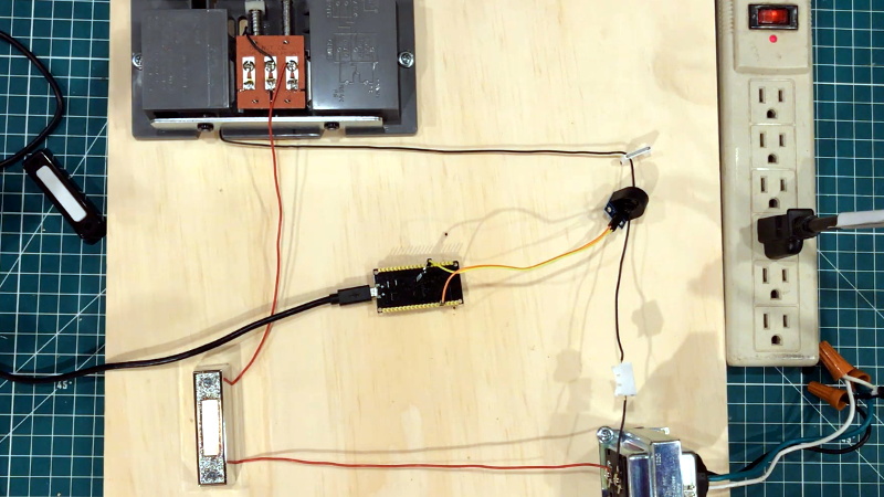
His solution only requires an inductive current sensor, which can be had for less than $1 from the usual overseas suppliers. One leg of the doorbell circuit is passed through the center of this sensor, and the sensor itself is connected up to your microcontroller of choice (here, and ESP32). The rest is software, which [AnotherMaker] explains in the video after the break. With the addition of a little debounce code, your microcontroller can reliably determine when somebody is out there jabbing the bell button; what you do with this information after that is up to you.
If you’re worried this method is too easy you could always try it with an optocoupler, or maybe convert the low-voltage AC to something your microcontroller can handle.


Why not use a dpst button? That sounds easier to me.
There is generally only a single 2 wire low voltage cable run to the doorbell. A dpst button would require running a new cable (difficult or impossible to do in an insulated exterior wall without damage in many cases). The cables are readily accessible at the transformer and chime locations in most cases.
Older houses use ac doorbells. Hook up a meter before you touch!
I’ve never seen a DC doorbell. Almost always 24VAC, like thermostats.
Optocoupler FTW.
Very different per country. my doorbell is 12V DC, my thermostat is 24V, also DC, like every other thermostat I’ve seen in Europe.
I deal with new construction and the typical door bells I run into still do 16 to 24 volts. However it all depends on the electrician for the cableing. I’ve seen two conductor, cat3 and cat5e used.
😂 ᒪ𝑜𝓁
I mentioned that as an option…if not in this video, another one. This just keeps everything stock and only requires momentarily disconnecting one wire in the system.
Next step a water squirter at the front door :)
Bring it on!
But what society really needs, is a water squirter for telemarketers.
That’s why I asked the question.
I leaned something from the video, which is more than I expected.
Thanks for watching!
You are welcome.
If you’re at the house you know someone’s ringing the doorbell. If you’re not at the house it doesn’t matter if somene’s ringing the doorbell.
I did have a third scenario. I work from home and my office is a building behind my house. I don’t need it a ton, but it’s really nice to have.
Scenario X+1: You are in the back yard (at home but out of earshot of the doorbell).
Well this is an example of how something like this can be done so just say for example you have an unmonitored alarm system. Use this as a basis to notify you when your alarm siren turns on or off.
In my case, I am in a detached workshop many times and cannot hear the doorbell.
I guess the lesson here is everyone’s lifestyle may not be the same as yours.
Is that just a plain current transformer? If so, it will be outputting AC into the analog input of the ESP8266. Not a real good idea.
It will be better to rectify the signal and limit the voltage to protect the ASP8266.
Otherwise, that is a great idea. I wish I thought of it.
My mod was to have a wireless doorbell transmitter button in place of the original button, and have it powered from the transformer. It achieves a similar result, but using a current transformer, I could have just powered the transmitter from its output. A lot easier!!
I recommend watching the video. He answers all of your questions there.
I did watch the video and it looks like he has just hooked a current transformer straight on the analog input. Unless I missed something.
Please expand on what that was.
It’s a current transformer module… there is already a resistor on the PCB on the bottom of the transformer.
But a resistor does not mean the output is not AC. That resistor “calibrates” the transformer.
It is not good practice to feed an AC signal into the analog input without some processing.
Offsetting the 0 current the half ADC voltage input will help, but still the voltage should be limited to be within the ADC input range.
Probably a better way to go in this instance is to convert to DC and then clamp the voltage to safe levels.
None of that appears to be done here.
Damage to the ADC input is a real possibility.
A resistor won’t remove the AC. You need an antiparallel diode to eat the AC component.
This is the problem with videos instead of circuit diagrams and code listings. I can look at the diagram and see what you’ve done. With a video, I have to hope you thought of (and answered) all the things I might ask.
I just mentioned in another comment, but for the vast majority of my videos the code in the description tell you everything you need to know. Connect this sensor between analog pin and ground. I usually comment well enough that unless there’s the occasional capacitor/pullup/voltage divider, there isn’t much of a need for a schematic for my arduino stuff.
That said, I do have a companion blog to my channel where I try to post all the relevant stuff, but COVID had me away from my house for 2 months, so I’m playing catch up.
Thanks for this. I will definitely double check the output of that sensor and report back when I can get back to my office. The project was originally done on an arduino mega with an Ethernet shield (which is a bit more forgiving), but I re-recorded the video last minute swapping over to an ESP32 to get the price down and accessibility up. Again, thanks for the feedback.
The specs say the max the sensor will output is 5ma, but it doesn’t say at what voltage. More exploration required.
Does Youtube allow you to put a schematic/diagram in the Comment section?
Not really. I have a blog along with this stuff but COVID had me away from my house for 2 months so I’m behind. Most of my videos don’t really need much of a schematic because it’s spelled out in the code. Like in this one, the code just says to hook the sensor between analog pin whatever and ground. It wasn’t really worth developing a schematic.
Except that it **IS** worth drawing a schematic. It seems you are doing things in a not really proper way. Best case, you have limited the current to the analog in pin and the ESD diodes in the processor are clipping off the negative voltage. Worst case, you are smacking the processor with too much current and will eventually kill the analog input and possibly the processor.
How much current can an Arduino (or ESP32) analog pin accept when the voltage is below ground? How much current can your sensing transformer supply? Have you done anything to limit the current? Damifino.
And how exactly did your reply help?
I would feed the bell voltage in a relay coil and hook the switch contacts to the MCU. Perfect galvanic separation.
This is what I did about 15 years ago, simple rectifier into a relay forked off an exposed bit of the wire I could get to. Originally lit up a bulb so I could ‘see’ the bell being rang when in the basement. Now toggles a pin on an ESP01 which posts the event via MQTT…
care to post the schemetics ? i am wondering if there is any 24 V AC coil relay I could use.
any idea which relay i could get to ?
Love this video and application – a great introduction to iot. A logical add would be to power the ESP from the doorbell transformer – like the led in the button in the vid. Would love to hear ( read ) your recommendation on 20VAC to 3.3VDC, and how that might impact your detector ( move the base amp from .07 to ? ).
I’ve been talking about this. I have another youtube friend who is doing this and so I figured I would let him do that part in his video and use his implementation as a shout out rather than pre-empting his video. Thanks for this. The next step is going to be shooting water from the doorbell and a few other goofy automations and then powering from the transformer.
I interface my doorbell with a microphone, no wires.
of course, not for the door opener (which I don’t have)