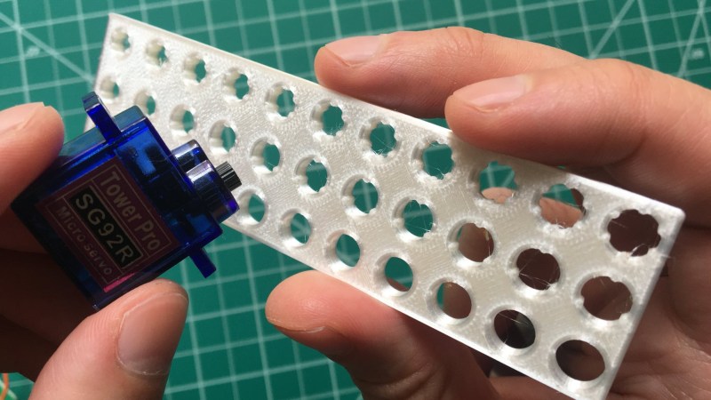
There is something to be said for brute force or trial-and-error approaches to problems, especially when finding a solution has an empirical element to it. [Tommy] perceived that to be the case when needing to design and 3D print servo horns that would fit factory servos as closely as possible, and used OpenSCAD to print a “Goldilocks array” from which it was possible to find a perfect match for his printer by making the trial and error process much more efficient. By printing one part, [Tommy] could test-fit dozens of options.
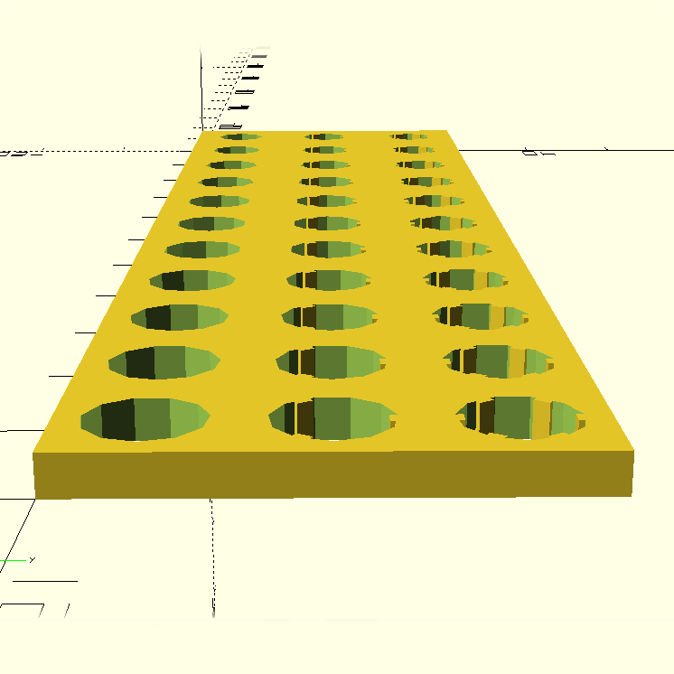 What made doing this necessary is the fact that every 3D printer has some variance in how accurately they will reproduce small features and dimensions. A 6.3 mm diameter hole in a CAD model, for example, will not come out as exactly 6.3 mm in a 3D-printed object. It will be off by some amount, but usually consistently so. Therefore, one way around this is to empirically determine which measurements result in a perfect fit, and use those for production on that specific 3D printer.
That’s exactly what [Tommy] did, using OpenSCAD to generate an array of slightly different sizes and shapes. The array gets printed out, servos are test-fitted to them, and whichever option fits best has its dimensions used for production. This concept can be implemented in any number of ways, and OpenSCAD makes a decent option due to its programmatic nature. Interested in OpenSCAD? It will run on nearly any hardware, and you can get up and running with the basics in probably less than ten minutes.


I generally do sooo many test prints when fitting something new.
Why have I never done it this way?
Thanks Tommy and Donald!
OpenSCAD is a nice touch! I do this a lot with the lasercutter, creating jigs for circular and square holes. Great for testing the fit of bolts, wire, etc.
One very important detail missing in the article, is that OpenSCAD “holes” (cylinder) will never be the size you specify if you don’t understand how they’re made : they are an approximation of a circle, a polygon fitting within the specified diameter. As such the printed hole will always be smaller than the diameter you specified. The OpenSCAD team is well aware of of this and it’s well explained in their faq, and there also a formula there to compute the diameter to pass to the software to get the desired result. A gotcha for newcomers for sure.
I’ve found both issues (approximate circles and printer accuracy) and the definitely compound each other. I’ve definitely done my share of “grid of ever increasing hole sizes” a few times.
I usually leave the $fn at the top of the file fairly low (like 30) while designing (to speed up render times), then crank it up to 200-500 depending on part sizes and tolenrences for cura. This helps with the “approximate” problem since a small circle made of 200 polygons is going to be pretty darned round. You also have to consider that the stepper motors are also linear x/y drives, so you’ll never get a *perfect* curve out of an FDM 3d printer anyway (resin printers have a finite resolution, but it’s high enough you’ll probably never notice). The larger the holes, the higher your $fn should be since it’s usually the absolute accuracy (not relative accuracy) that’s important.
The main reason 3d printers print holes the wrong size is because the plastic is not super viscous when it comes out, so it tends to “drag” around the inner diameter a bit, closing the hole slightly. As the hole size increases, the angle (relative to the circle’s tangent) the printer is “dragging” the molten plastic by the time it hardens decreases very quickly, so the effect is mostly seen in small holes (less than 10mm in my experience). This makes it tricky to predict how much hole shrinkage you’ll get since the variance depends on your filament material, temperature, feed rate and hole diameter, hole orientation and probably your nozzle diameter as well (I’ve only done .4mm so far). Also, don’t forget that while horizontal holes don’t have the drag problem (since they’re effectively rectangles stacked in the slicer), but the tops tend to sag more as your hole size increases.
So the drag problem mostly affects smaller holes, while larger holes sag and are more affected by the $fn value, but medium holes can sometimes suffer from multiple factors if you’re not careful. So if I have a print that’s going to take a while and has holes that need to be accurate, I’ll usually do a quick test print with the hole sizes (in their final orientations) as a double-check before committing hours (and filament) to the final print.
I used a different approach. set $fn=0, $fa=0.01 then use $fs to set the resolution. You can use $fs=1 or 2 for draft, and set to 0.2 to 0.5 for “quality”.
I’ve found $fn to be not generally useful. In my common OpenSCAD include file, I use $fa=1; $fs=0.5;
$fs=0.5 means that the circles will be split in segments no longer than 0.5mm. This ensures that circles large and small will have consistent precision.
$fa=1 means that the circles will be split in at least 1-degree arcs. Otherwise the default of 12 will be used and you will get no more than 30 segments in a full circle
If you’re doing polygons instead of circles, you inevitably have to choose the inside diameter or the outside diameter. (Inscribed or circumscribed circles.) One is good for holes, the other is good for pegs, neither one is “right”. OpenSCAD sizes “circles” using the outside diameter.
If you want to scale up your holes, you can increase the outside radius/diameter by a factor of how many sides it has.
function corrected_radius(r, n = 0) = r / cos(180 / n);
Nophead did this with his “polyholes” waaay back in the day: https://hydraraptor.blogspot.com/2011/02/polyholes.html
There’s other factors, like drag on the plastic and extrusion multipliers and backlash and simple tolerance in the part that will make you still want to add some part/machine specific slop, so this procedure is a good one.
When I need an important fit, I always plan to drill it out or print a couple of the critical bits until it works. This disciplined approach sounds good to me!
That’s pretty sad to be honest. You get what you pay for. This seems to be the CAD software of choice for people who don’t do much CAD.
I mean I know the old cliche is that you get what you pay for, but for openSCAD you certainly get a lot more than nothing. Which is what you pay for. It’s pretty nice all things considered. There are quirks to be taken into consideration, but then again I use Creo at work and that piece of trash has a billion problems. It costs a shitload of money. Their support is terrible. Just refreshing the license annually is like pulling teeth.
“This seems to be the CAD software of choice for people who don’t do much CAD.”
Yes, and people already familiar with programming languages not wanting to go through the often steep learning curve associated with CAD software they will so rarely use with the GREAT additional benefit of allowing easy user modifications of 3D parts through dirt simple modification of input values in well commented OpenSCAD scripts using the free and easy to use OpenSCAD software.
It’s easy to give OpenSCAD a hard time: it’s not really CAD in a lot of ways, but it’s a shame similar code-based generation features are so hard (or impossible) to access in other CAD packages.
I think it’s a miserable way to design most things I design with solid modeling tools, but sometimes I need to to something generative by the numbers, and I’m glad it exists. And I see how it really suits some people’s mindsets or some designs.
Tooooo be fair, Catia has the same/similar issue. You have to manually set the polygon count to be really high when printing with it, less you run into the exact same problem.
Quite frankly, I’ve never used a CAD that didn’t have a million and a half quarks, though where the quarks are located depends on the software.
This is useful not just because the printers are different, but also servo horns are varying. Thanks for an idea!
I did a similar project, with an extensive survey of 3D printing service results. I submitted to HaD, but they didn’t run it…
https://saccade.com/blog/2019/12/fit-testing-block/
I have an alternative approach. Dial up $fs or $fn, just model the hole as is, print it, then get my drill out and drill the final size.
Works every time.
That only works if the hole is round… these don’t appear to be.
As remarked below: these are spline-keyed holes, can’t just drill and call it a day
Cool experiement. It could use a summary table at the end showing the process/company, cost, and tolerance. I’d add that and submit it again.
Slightly related, if you want to make good fitting custom horns for the commonly cloned MG996R or similar servos with a metal spline, I disassembled one and mounted the spline and final gear in the end of my hot air soldering nozzle. It then heats up with the small flow of air through the M3 internal hole and that which flows over the gear and makes a nice heat former into a slightly undersized hole in your horn material (delrin is really nice for this). Takes a few practice attempts to know how deep / hot to go, how to keep the former parallel with the hole and when to pull the spline out. But it allows you to put full servo torque on your custom horn without tearing the spline apart.
I bet you don’t even need heat, just a drop of acetone or appropriate solvent in the hole and let it sit a few mins, then mash it in, leave until solvent evaporates.
I thought I’d look it up and here’s a list for Delrin/POM/Acetal https://www.calpaclab.com/acetal-polyoxymethylene-chemical-compatibility-chart/
Acetone doesn’t look like it would work though on Delrin.
Perhaps a well-handled press would also let you do some scraping of the spline profile, if you can pull the former part out. Perhaps a lever under the gear but they’re made of fairly soft metal and these days all the clones have a cast spline with rounded edges so may not work as well as the original brass ones. Apparently the proper TowerPro ones now have aluminium splines so they might not work as well for this as the brass and “grey metal” knock-offs.
Hah, yeah, I was still thinking 3D printed ones, not the delrin. Though actually I’m surprised delrin yields much to heat when thinking about it, though it resisted heat up to over 220C ish then started decomposing.
I have some 10mm white POM plate and I think I set the hot air to around 240C. It took some force to push the metal into the hole but once it was in and there was good thermal contact between the metal and the POM it softened quickly (need to support the metal). It went slightly more translucent where it was melted.
I print a “right sized” hole for the metal spline, spray the spline with some release agent and put 5 minute epoxy in the hole. This makes a perfect fit. The horn can be adjusted in small steps determined by the grooves in the spline.
Nice. Do you do anything like blanking off the threaded hole or installing a piece of threaded rod to stop the epoxy oozing into places where it would prevent the bolt from securing the horn afterwards? Or don’t you use the centre hole to secure your horn.
I just smear a tiny bit of epoxy. It does not get into anything else. The spline is about 5.5mm diam. The print goes over then end of the spline with as 3mm hole.
Thanks!
Just did this for picking the right laser kerf for press fit parts, using OpenSCAD actually.
https://hackaday.io/project/170507/log/178984-laser-kerf-test
Back in the 90s, I used to cut a horn out of 1/16 or 3/64 plywood. Then cut a chunk out of some too soft for much else balsa, press the servo into it, pull it out, position the balsa block on the plywood, then flood with cyanoacrylate (super/crazy glue) and leave to dry. The soft balsa would soak up so much cyano, that it was basically a solid chunk of plastic. When completely dry I’d drill hole through for screw.
I can see this being useful if you print a ton of similar parts, but there are so many other factors involved when dealing with tolerances. The same 6.2mm hole on say a flat slab rectangle will definitely not turn out the same if that ‘same’ hole is printed into a form factor where the hot nozzle and material placement is spending more time being printed nearby. If that makes sense. Heck, that slab could affect the hole tolerances just by having a different infill value.
I can see this being relevant when you go from a two prong servo horn to a 4 or 6 prong one. Due to the increasing amount of material along sides of the hole keeping it warm and cozy. Then you think you got it sussed and do a right angle one, and your hole isn’t round.
Anyone who has ever done this knows that the “optimal fitting” hole is ALWAYS the very largest or very smallest one you make, or very close to being that. I’ve never had the satisfying situation where it came out to be a value that was comfortably in the middle of the range I was testing.
FWIW in the visual special effects (“VFX”) business, this approach is often referred to as a “wedge”: homing in on the best value for a parameter by rendering a still frame multiple times with the value animating between two values.
It helps a lot to see where to split the difference, just like this 3D printing method helps to figure out the perfect fit.
Anyway I refer to this technique as “printing a wedge.” Give it a try :)