The oft-quoted saying “all models are wrong, but some are useful” is a tounge-in-cheek way of saying that at some level, tools we use to predict how the world behaves will differ from reality in some measurable way. This goes well beyond the statistics classroom it is most often quoted in, too, and is especially apparent to anyone who has used a GPS mapping device of any sort. While we might think that our technological age can save us from the approximations of maps and models, there are a number of limitations with this technology that appear in sometimes surprising ways. [Kyle] has an interesting writeup about how maps can be wrong yet still be incredibly useful especially in the modern GPS-enabled world. Continue reading “Misleading GPS, Philosophy Of Maps, And You”
accuracy11 Articles
The Inner Machinations Of The Arduino Are An Enigma
Arduinos have been the microcontroller platform of choice for nearly two decades now, essentially abstracting away a lot of the setup and lower-level functions of small microcontrollers in favor of sensible IDEs and ease-of-use. This has opened up affordable microcontrollers to people who might not be willing to spend hours or days buried in datasheets, but it has also obscured some of those useful lower-level functions. But if you want to dig into them, they’re still working underneath everything as [Jim] shows us in this last of a series of posts about interrupts.
For this how-to, [Jim] is decoding linear timecodes (LTCs) at various speeds. This data is usually transmitted as audio, so the response from the microcontroller needs to be quick. To make sure the data is decoded properly, the first thing to set up is edge detection on the incoming signal. Since this is about using interrupts specifically, a single pin on the Arduino is dedicated to triggering an interrupt on these edges. The rest of the project involves setting up an interrupt service routine, detecting the clock signal, and then doing all of the processing necessary to display the received LTC on a small screen.
The project page goes into great detail about all of this, including all of the math that needs to be done to get it set up correctly. As far as general use of interrupts goes, it’s an excellent primer for using the lower-level functionality of these microcontrollers. And, if you’d like to see the other two projects preceding this one they can be found on the first feature about precision and accuracy, and the second feature about bitbanging the protocol itself.
Time And Accuracy In Las ATMegas
Do you ever have to ensure that an exact amount of time passes between two tasks in your microcontroller code? Do you know what’s the difference between precision and accuracy? Today, [Jim Mack] tells us about pushing timers and interrupts to their limits when it comes to managing time, while keeping it applicable to an ever-popular ATMega328P target! Every now and then, someone decides to push the frontiers of what’s possible on a given platform, and today’s rules is coding within constraints of an Arduino environment. However, you should check [Jim]’s post out even if you use Arduino as a swearword – purely for all of the theoretical insights laid out, accompanied by hardware-accurate examples!
This will be useful to any hacker looking to implement, say, motor encoder readings, signal frequency calculations, or build a gadget processing or modifying audio in real time. To give you a sample of this article, [Jim] starts by introducing us to distinctions between precision and accuracy, and then presents us with a seemingly simple task – creating exactly 2400 interrupts a second. As much as it might look straightforward, problems quickly arise when clock crystal frequency doesn’t cleanly divide by the sampling frequency that you have to pick for your application! This is just a taste of all the examples of hidden complexity presented, and they’re accompanied with solutions you can use when you eventually encounter one of these examples in your hacker pursuits. In the end, [Jim] concludes with links to other sources you can study if you ever need to dig deeper into this topic.
Keeping our projects true to the passage of time can be an issue, and we’ve been at it for ages – calibrating your RC oscillator is a rite of passage for any ATTiny project. If you ever decide to have an interrupt peripheral help you with timing issues, we’ve gone in-depth on that topic in the past, with a three-part series describing the benefits, the drawbacks and the edgecases of interrupts. Going for a more modern target? Our piece on using interrupts with STM32 is a great path for trying out tools of the modern age.
NTP Server Gets Time From Space
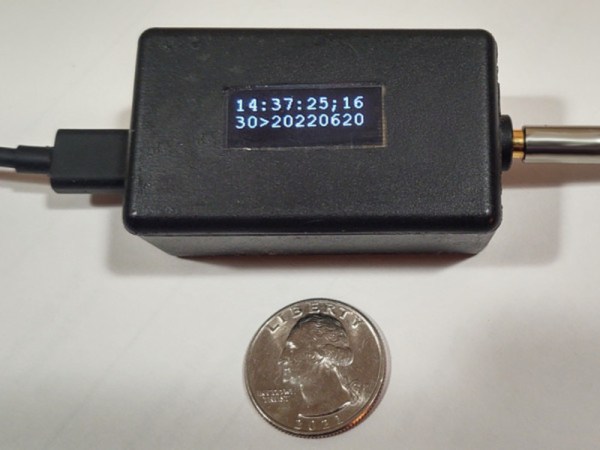
Cheap GPS units are readily available nowadays, which is great if you have something that needs to be very precisely located. Finding the position of things is one of many uses for GPS, though. There are plenty of ways to take advantage of some of the ancillary tools that the GPS uses to determine location. In this case it’s using the precise timekeeping abilities of the satellites to build a microsecond-accurate network time protocol (NTP) server.
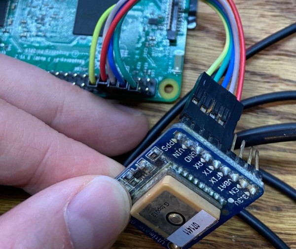
GPS works by triangulating position between a receiver and a number of satellites, but since the satellites are constantly moving an incredibly precise timing signal is needed in order to accurately determine location from all of these variables. This build simply teases out that time information from the satellite network and ignores the location data. There are only two parts to this build, a cheap GPS receiver and a Raspberry Pi, but [Austin] goes into great detail about how to set up the software side as well including installing PPS, GPSd, and then setting up the actual NTP server on the Pi.
While this is an excellent way to self-host your own NTP server if you don’t have Internet access (or just want to do it yourself), [Austin] does note that this is probably overkill on timekeeping as far as accuracy goes. On the other hand, the Raspberry Pi has no built-in real time clock of its own, so this might actually be a cost-competitive way of timekeeping even when compared to something more traditional like a DS3231 RTC module.
A Savage Discussion Of Measurement And Accuracy
It’s commonly said that the great thing about standards is that there are so many of them. Of course, that’s talking about competing standards. But there’s another kind of standard that you want a lot of: Measurements. Without standard measurements, the Industrial Revolution wouldn’t have been facilitated to the extent it was. The illustrious [Adam Savage] takes a deep dive into the art of measurement in the video below the break, and if you have 45 minutes to spare, you will not be disappointed.
We don’t want to give away any big spoilers, but [Adam] starts out with things we can all relate to if we’ve done any kind of measuring for accuracy: measuring between the given lines on a standard tape measure. From there he goes into calipers and other tools for measurement.
Then, out come the Big Guns. The ceramic blocks so flat that… well you’ll just have to watch it. But the discussion goes deep into nanometers, microns, and jeweled movements.
Whether you’re a machinist or a garage hacker with nothing more than a stick welder and an angle grinder at your disposal, or anywhere in between in any segment of being a maker, this video is for you. [Adam]’s enthusiasm is off the charts in this diatribe, and we have to admit- it’s contagious! We’ve never been so excited about measuring things.
Of course, if you need to measurement tool, you can just build a measurement tool. It’s all subjective, after all.
Continue reading “A Savage Discussion Of Measurement And Accuracy”
Digital Pregnancy Tests Use LEDs To Read Between The Lines
[Foone] saw a tweet a few weeks ago alleging that digital pregnancy tests are a rip-off. Regular, cheap tests have an absorbent strip running the length of the plastic, with one end exposed for collecting urine. A few excruciating minutes later, a little plastic window in the middle will show one line, two lines, or a plus or minus sign depending on the presence of human chorionic gonadotropin (HCG) in the urine.
 As it turns out, at least two digital tests out there are the exact same thing, but with more steps. Instead of a window, they include circuitry that interprets the lines and publishes the result to a little screen in plain English. It can even tell you if you’re doing it wrong by flashing a little RTFM icon.
[Foone]’s teardown reveals a CR1616 coin cell, an 8-bit microcontroller, and a little phototransistor setup that shines LEDs on the strip and reads the incoming light. Unfortunately, the micro is the mask ROM version, so [Foone] can’t reprogram it to run Doom.
The original tweet’s author is probably not alone in assuming that digital tests are supposed to be more accurate somehow. We think the accuracy claim is more about removing the frazzled and/or incompetent human variable from the equation. If the test interprets the results for you, then there’s no mistaking the results, which is technically a higher degree of accuracy. But if you’re in doubt, you get a test from a doctor.
There’s been some discussion about the e-waste aspect of these all these tests — that it’s a shame to produce a microcontroller just to pee on it and throw it away. Sure, you could look at it that way, but unlike a lot of e-waste, these are tools. It’s unfortunate that this is the industry’s idea of higher accuracy, but what should we expect? It’s just testing for the presence of a hormone in urine. Interpreting the results is up to the viewer. We should probably be astounded that they got the cost down to two for $7.
Many people choose to wait a while to start spreading the news. With a Bluetooth-enabled pregnancy test, everyone can find out together.
Thanks for the tip, [Jay]!
Finding Perfect Part Fits With The Goldilocks Approach (and OpenSCAD)
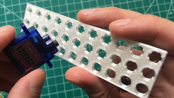
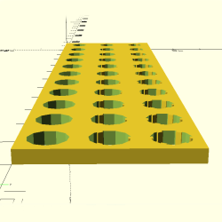
There is something to be said for brute force or trial-and-error approaches to problems, especially when finding a solution has an empirical element to it. [Tommy] perceived that to be the case when needing to design and 3D print servo horns that would fit factory servos as closely as possible, and used OpenSCAD to print a “Goldilocks array” from which it was possible to find a perfect match for his printer by making the trial and error process much more efficient. By printing one part, [Tommy] could test-fit dozens of options.
 What made doing this necessary is the fact that every 3D printer has some variance in how accurately they will reproduce small features and dimensions. A 6.3 mm diameter hole in a CAD model, for example, will not come out as exactly 6.3 mm in a 3D-printed object. It will be off by some amount, but usually consistently so. Therefore, one way around this is to empirically determine which measurements result in a perfect fit, and use those for production on that specific 3D printer.
That’s exactly what [Tommy] did, using OpenSCAD to generate an array of slightly different sizes and shapes. The array gets printed out, servos are test-fitted to them, and whichever option fits best has its dimensions used for production. This concept can be implemented in any number of ways, and OpenSCAD makes a decent option due to its programmatic nature. Interested in OpenSCAD? It will run on nearly any hardware, and you can get up and running with the basics in probably less than ten minutes.


