Most of us are familiar with the tools available to create circuit diagrams, as generally that’s the first step towards producing a custom PCB. But that about the cables and wiring harnesses that don’t live on your board? How do you easily document the rat’s nest perfectly logical wiring of your latest and greatest creation?
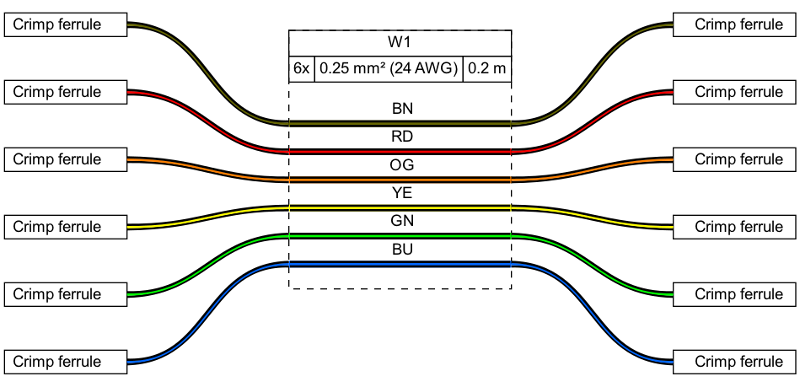
That’s precisely the question that led [Daniel Rojas] to create WireViz. This open source Python tool takes human readable input files and turns them into attractive and functional visualizations of where all the wires in your project are going. It can even be used to generate a Bill of Materials that documents the lengths of wire required and types of connectors needed to hook everything up.
If you’re still using pre-made cables to connect all of your components together, than you might not immediately see the benefit of a tool like this. But as we’ve talked about in the past, the creation of custom wiring harnesses is something that serious hardware hackers should become familiar with. Yes it takes more effort, but the end result is worth it. With a tool like WireViz, the creation of a bespoke harness for your next project just got a little bit easier.
[Daniel] has done a fantastic job documenting this project, providing not only a tutorial on how to feed and care for your WireViz, but a gallery of examples that shows off the kind of complex wiring the tool can help make sense of. But there’s plenty more to be done, and he’s happy to get feedback or code contributions from anyone who wants to get involved.


This looks very cool, and potentially incredibly useful.
I kind of like it. I just make them in illustrator for the time being, but that has way too much bloat and Adobe is the worst software company in the history of mankind and I hate them. However I think this would take off a lot more if it had a simple GUI of some kind. Just click and create nodes, type in fields, maybe drag noodles between them for wires. Just like any other node-based editor. This seems like a natural use for that.
But then again I know a lot of electronics people also don’t wanna muss around with GUI and just keep things CLI.
Hmm… Adobe… Microsoft…. a tough call. :-D
Aside from this really cool tool you could try to use inkscape instead of illustrator.
If you want to get away from Adobe AI you can use Inkscape instead, it does a lot of the same stuff, but free and open source.
Very nice work. I am putting this to good use rewiring some old construction equipment harnesses.
I love this project but it has driven me crazy trying to find an older post on how to hand tie string to keep harnesses together. It was used by Ma Bell or some other phone company way back in the day. I’ve looked in Retrotechtacular. Anyone else remember seeing it?
You mean “Cable Lacing”?
Try https://www.flight-mechanic.com/lacing-tying-and-cutting-wire-bundles/
What you’re looking for is called ‘cable lacing’ We used it to train wiring with it in the Navy. Quick google search will show several how-to videos.
Yes, the ARRL Radio Amateur’s Handbook from the early 1960s. Send me an email at jpotter @ jpotter.com and I’ll send you a pdf of the page.
Even much more recent editions had a section on cable lacing.
Very nice project. My only addition would be to have a top or bottom view of the connector – at least a positional layout showing pin numbers relative to each other. If you say, for example, a 2×8 connector. Even if you include the part number, it’s confusing to the reader how you’ve numbered the pin holes – eg. down the long side and back up or vice-versa.. etc.
Forgot to add – also pin number relative to a clip position. It would be difficult to have a dimensionally accurate diagram. But maybe a simple line-art language for describing how to draw one.
Something very similar would be useful to describe computer network wiring on physical level… Especialy if position of the wires would be tied to GPS coordinates and you could have cable with several optic fibers, each of these fibers could contain several WDM colors, each color would then contain VLANS, VLANS would contain Q-in-Q and so forth…
I was actually talking about this exact idea with somebody earlier. If you replace the connectors with switches/routers/computers, and the pins with ports, you could use this tool as-is to create network topology maps. If somebody cared to, creating a slightly more network-centric fork seems like it would be pretty straightforward.
A commerical product exists, it’s called Patchmanager. It has Visio like stencils for most hardware/patch panels. You cand use SNMP for it to semi-figure out what is going on at the physical layer. And the coolest feature it has is that if you are managing a large cable plant – you can create a “work order” where you might have a tech go patch from panel A to panel B in cab 4, and then B to C in cab 5 and they can then mark the work complete and it updates the diagrams.
Have a look at netbox if your after a tool for recording network infrastructure. https://netbox.readthedocs.io/en/stable/
can this be done in a node red format ?
Looks good. It would be great to have a way to specify multicolor insulation, like in Ethernet cable.
Looks like it supports DIN 47100. Should give you a large spread of different wire colors.
I wonder if this software can somehow be interfaced with the custom cable manufacturing service at, say, Dirty PCBs? Some kind of export/import step? That would make it into a CAD system for cables that would be equivalent to existing toolchains for PCBs…
I think that importing/exporting shouldn’t be that hard… But you would need to know the data format that they provide/expect in order to do it.
Is there a similar tool for lab network wiring?
I’ll have to give this a try. Almost all wire harnesses in my projects are custom since the projects are one-offs I do for my own amusement and I simply don’t have the collection of pre-fab interconnects to draw from. Spools of wire and a small assortment of connectors can go a long ways. I’ve started trying to diagram them in KiCad. But this will probably be nicer. At least the sample image above looks nicer. :-)
This is very slick and I will be checking it out. Most of my cable assembly drawings are actually done in Visio because I was an expert in Visio before I had access to any CAD programs I could use at a previous employer. I create my own Visio stencils with wire, connectors, etc and then create complete drawings using standard mechanical drawing page templates that have ECO, Title, and BOM blocks. When people see my drawings, they assume I used AutoCAD or Solidworks. I usually laugh and say, “I wish”. Most people don’t know about the power of Visio. It has some really cool features hidden in the toolbars and with tools like join/subtract/union, I have made some very intricate shapes. I just wish it wasn’t so expensive so I could use it more at home.
I could see people asking for a lot of feature additions, some already mentioned in other comments like connector pinning, to make this extremely useful.
This is a (brilliant) language overlay for GraphViz – a text-driven diagramming tool. The diagramming ‘language’ is not all that difficult to grok. Those of you who are asking for particularly technical features probably have the technical chops to implement them yourselves.
This is excellent tool to document my custom wire harness I made for my car.
I wonder if it works too for computer network.
Let me begin by saying this is a very cool and useful tool!
What I’m missing is flexibility of workflow. As it is now, the wiring must be number based it seems. So I can label pin 1 on X1 as GND, then label wire 1 of W1 as GND, and pin 6 of X2 as GND. But then I must connect them as X1:[1] W1:[1] X2:[6], but I have already labeled everything, I want to be able to do X1:[GND] W1:[GND] X2:[GND], or even when the wire is designated a color X1:[GND] W1:[BK] X2:[GND]
I’m late to the party but I just found where it does that…
File from the examples….
//start
connectors:
Key:
type: Phone Connector
subtype: male 3.5
pinnumbers: [T, R, S]
pinout: [Dot, Dash, Ground]
show_pincount: false
cables:
W1:
gauge: 24 AWG
length: 0.2
color_code: DIN
wirecount: 3
shield: true
connections:
–
– Key: [S,R,T]
– W1: [1,2,3]
–
– Key: S
– W1: s
//end