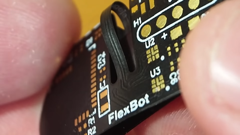
It is not a secret that flexible PC boards can bend. But despite the substrate’s flexibility, you can’t really fold them completely over. That bothered [Carl] so he developed a hinge design so that he can fold a board completely in half. You can watch a video showing an example, FlexBox, below.
Normal boards can fold over, but the copper traces can’t tolerate a very tight bend radius. [Carl’s] trick is to make the folding part have no traces at all. Only a small bridge carries traces between the two halves and it is allowed to bend almost like an interconnecting cable.
It’s true that a board-level interconnect between two PCBs could also be used but there is something attractive about having the entire assembly as one piece, especially if you are using a flex PCB anyway. We don’t have any data, but we imagine the flexible PCB is more reliable than a socket and plug and adds no additional cost.
[Carl] is the master of flexible boards. He’s done videos on cheaper prototyping for hybrid flexible/rigid PCBs using stiffeners. He’s used them for jumping robots and sort of holographic optical displays. If you want more ideas about flexible PCBs, check out the results of last year’s flex PCB contest.


> flexible PCB is more reliable than a socket and plug and adds no additional cost.
OSH charges $5/in^2 for regular PCB, but $10/in^2 for their flex. So you are paying 2X per sq footage. It doesn’t take a very large PCB are to pay for connectors.
Other places might be cheaper, but there is always a cost premium to flex. There are limitations to what is available cheaply . e.g. It is easier to get regular 4 layers PCB than flex
My thoughts as well. You definitely don’t get flex for free. Flex is typically more expensive than 2 or 4 layer FR4, also when doing bigger runs. And it’s much more demanding in the pick and place machine, so if you’re running production volumes that will be a cost driver, and flex/sag/twist might limit the panel size – also a cost driver.
There was flexible circuit board.
In the July-August 1971 issue of Elementary Electronics, there was a “crystal radio” for the aero band at 108MHz. A tuned circuit and germanium diode feeding an audio amplifier. Since it was passive on RF, it coukdn’t interfere with radios in the cockpit.
But, they specified a flexible piece of circuit board, so the project could be hidden. I think they specified a blank board from the Allied Radio catalog, but maybe it was premade and yiu sent away for it.
I don’t know the material, but obviously it had copper foil laminated to it.
I don’t recall ever seeing that board mentioned again.
Sadly, that americanradiohistory.com site has an incomplete issue, so the article is missing.
Flexible circuits have been used in the automotive industry since at least the early 1970’s in instrument panels.
I’ve never tried flex pcb, but I could like to try replacing some cables. Thinking that the FFC cables aren’t cheap either. Don’t know for sure, but i would like to do the math. Less parts less hassle, but i’m just speaking out of the ignorance over here.
Why didn’t he just use a standard PCB with more layers?
Why didn’t he wait until he had tested his design?
I wish hackaday wouldn’t waste my time with articles that can be summed up a “I did something, but haven’t tested it”.
tldr: he’s making a jumping bot, standard pcb with more layers can’t jump.
Decent 2020 implementation of 1980’s technology.
This is a good tip on how to achieve tight bends without having small bend radii on the conductors section of a flex/rigid flex design – no doubt, but it’s not in any way novel, I’d say it’s just common practice. Wurth electric even has a version of this method as an example in their rigid flex pcb stack up sample kit.