Unless you’re in a carnival funhouse, mirrors are generally dead flat and kind of boring. Throw in some curves and things get interesting, especially when you can control the curve with a touch of your finger, as with this variable surface convex mirror.
The video below starts off with a long but useful review of conic constants and how planes transecting a cone can create circles, parabolas, or ellipses depending on the plane’s angle. As [Huygens Optics] explains, mirrors ground to each of these shapes have different properties, which makes it hard to build telescopes that work at astronomical and terrestrial distances. To make a mirror that works over a wide range of distances, [Huygens Optics] built a mirror from two pieces of glass bonded together to form a space between the front and rear surface. The front surface, ground to a spherical profile, can be deformed slightly by evacuating the plenum between the two surfaces with a syringe. Atmospheric pressure bends the thinner front surface slightly, changing the shape of the mirror.
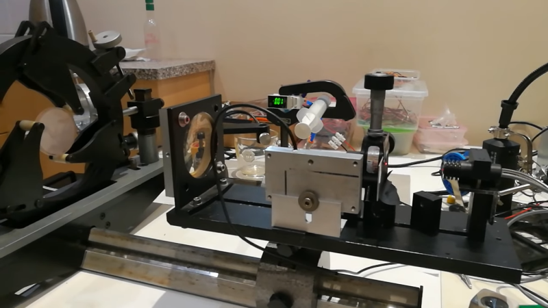
[Huygens Optics] also built an interferometer to compare the variable mirror to a known spherical reference. The data from the interferometer was fed to a visualization package that produced maps of the surface shape, which you can easily see changing as the pressure inside the mirror changes. Alas, a deeper dive into the data showed the mirror to be less than perfect, but it’s fascinating to think that a mirror can flex enough to change from elliptical to almost parabolic with nothing more than a puff of air.
We’ve seen a couple of interesting efforts from [Huygens Optics] before, including this next-level spirit level. He’s not all about grinding glass, though — witness this investigation into discriminating metal detectors.


His youtube channel isn’t huge- but its a wonder look into the dark arts of bespoke lens and optics manufacturing.
I highly recommend checking it out, really impressive stuff he does
I wonder if thin metallized foil could be used instead of glass in this case to form a mirror. Using just an air pressure (lowering air pressure in closed section) could form concave surface.
I did exactly that on a small scale using a piece of a metalized mylar “rescue blanket” stretched over the edge of a short section of 12″ PVC pipe. I wanted to see if it could be used for a solar concentrator. I closed the back side of the pipe with a piece of acrylic and sealed it up using silicone. When I drew out some air it formed a nice concave surface and was able to set some leaves on fire. I never scaled it up to the 1m diameter that was my original intention.
I found some interesting things- the mylar blanket allows a surprising amount of light to pass through. Also, the edge of the film support frame is critical – any error in that edge creates a distortion in the film that is clearly visible when you look at your reflection in it. That means that unless you go to a lot of effort, it will be useless for any optical projects other than noncritical stuff like solar concentrators. The stretching is critical, too, and has to be done uniformly- if not shape of the concave surface will not be uniform. I used a bicycle tire tube stretched over the pipe to do the film stretching and it seemed to work well. The stretched film vibrates with every sound and movement of air, again making it useless for anything like a telescope mirror. Since the chamber behind the stretched “mirror” is sealed, the focal length will change with changes in temperature and barometric pressure, too. The structure that supports the “mirror” would have to be very rigid mechanically- its own weight would tend to distort the shape of the mirror.
One project I had in mind for this was a wall mirror that would be completely sealed. As barometric pressure and temperature change the mirror would go from flat to convex to concave giving the reflection a different appearance from hour to hour and day to day.
> Since the chamber behind the stretched “mirror” is sealed, the focal length will change with changes in temperature and barometric pressure, too.
Barometric pressure changes should be possible to eliminate by connecting a closed chamber behind the mirror with open-air through U-shaped glass tube filled with mercury (kind of barometer). In such case lowered pressure in closed chamber will stay constant.
> The structure that supports the “mirror” would have to be very rigid mechanically- its own weight would tend to distort the shape of the mirror.
I think that for larger mirrors of this type, even the film’s own weight would have an impact on the distortion.
Maybe filling the chamber with photocurable resin, then curing after forming a concave mirror could make it more useful.
That’s cool! If you documented you work, please think about submitting it to Hackaday! (Or post a link if you have already posted it somewhere else)
I’m about three years late, but still hoping you see this.
although your idea is very impressive, as you mentioned there are many problems that come with it.
it appears that most of those problems could be solved using something thicker and more rigid than a thin “rescue blanket”. I’m working on a project much like yours using a 1mm thick polyvinyl chloride mirror. from a couple of experiments I have already done, it seems to work well.
there, of course, are still some problems that remain like the mirror heating up and changing the focal length, the vibrations are also still a problem while it will vibrate much less than a thin film like yours, it still will vibrate. tho I’m not really sure how much, there are a lot of physics papers in this topic (vibrations in membranes stretched under pressure) there really is not a surefire way of knowing how much this will affect the image quality without testing it first. I’m thinking of using the schlieren method to see how good the quality of the mirror will be, but I currently have no idea how the vibrations affect the image.
any thoughts on this project will be appreciated.
Bernard Schmidt devised this technique in 1930 for his Schmidt camera (which led to the modern highly popular Schmidt-Cassegrain telescope). The corrector lens at the front of the camera/telescope has a complex shape; the central area is very slightly convex while the outer region is slightly concave. Schmidt made a metal pan with a diameter somewhat smaller than the lens, and with an edge that was machined accurately round and ground very flat. The lens blank was centered on this pan and a vacuum applied.
The distortion of the glass was such that when the upper surface was ground and polished to a sphere (the easiest optical surface shape to obtain) and the vacuum was released, the glass plate would spring back to the desired shape.
The method isn’t quite accurate enough for extreme precision but was adequate for initial work.
What would be cool is to figure out is how to scan a “makeup/shaving mirror” for errors from true parabolic, then 3D print a mirror cell to epoxy it to with a sandbag pressing it down or something, calculated to correct it. Yes I know, tons of details to figure like how to front surface silver it etc. Not thinking it’ll get into fractions of a wavelength accuracy, but could be used for big low mag light buckets for the gee whizz deep sky gawping.
https://skyandtelescope.org/wp-content/uploads/Adler-MirrorFlex.pdf
Nice, I kept pondering that sort of thing, epoxying a big bolt to the middle and pulling.