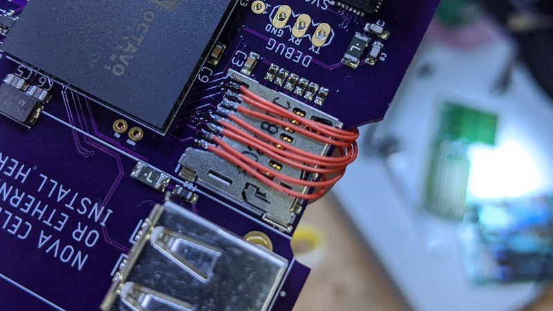
If you’ve got a few self-designed PCBs under your belt, you probably know the pain of missing some little detail and having to break out the bodge wires to fix it. So we feel for [Arsenio Dev], who placed an SD card slot next to an SoC, only to find that it was the wrong way round. Rather than tossing it in the bin, he decided to employ a particularly crafty set of bodge wires that curve over the board and connect to an SD card adapter on the other side.
Our attention was taken by the board itself, he’s posted little information about it and taken pains to conceal one of the pieces of text on it. Since it has an Octavo Systems BeagleBone-on-chip, a slot for a cellular modem, and a connector marked “CONNECT AERONET HERE” which we are guessing refers to the Aeronet sun photometry network, we’re guessing it might be a controller for remotely-sited nodes for that system. Either way it’s enough to have us intrigued, and we wish him every success with the next spin.
Meanwhile, this certainly isn’t the first PCB CAD fail we’ve brought you.


If there is a bunch of these boards already made, maybe some sort of “riser” or breakout board could solve the case. A small board that would be soldered right over the original SD card slot (removing it first, please), but routed to the correct position – basically, the same solution as the wires, but on an elegant package.
With flex PCB being so thin, it could be a tiny interposer sitting between the signal pins the the pads while keeping the existing mechanical pads for anchoring the socket.
You could probably do a very simple one with a square and a triangle of clad board to solder to what ground plane you could find (or epoxy it) and brace vertical mounting of the card carrier, so you can sneak a card in behind the socket.
Micro-SD adapters are awesome for hacky-fixes. You end up with loads of them, and for those who don’t know the pin spacing on an SD card is close enough to 0.1″ that you can just shove a row of 0.1″ pin headers on there, solder them, and hey look, it’s a micro-SD breakout usable in a breadboard that breaks out all of the pins, rather than the typical 7 most purchasable ones do.
“You end up with loads of them, and for those who don’t know the pin spacing on an SD card is close enough to 0.1″ that you can just shove a row of 0.1″ pin headers on there, solder them, ”
I hadn’t considered that.
Thanks!
Just be careful about the soldering. I got a bit spoiled by plastic parts that are meant to survive reflow ovens. SD-to-Micro SD adapters are notably not made of high temperature plastic.
It’s not exactly challenging soldering. You need to work somewhat efficiently, with flux and a clean tip, but it’s basically on a par with through-hole soldering in general. The nearby plastic will melt some, but not anything important.
Sometimes you need your higher wattage iron for the more delicate jobs, 1 second dab soldering, you’re done before the plastic even says “Hey is it a bit warm in here or is it just me”
60W to 80W and good temperature control. The only unregulated soldering iron I have is a €5 part (30W) in the car tool-bag for some completely unforeseen repair jobs – still better than using the jet-flame lighter :-)
Though if you REALLY don’t wanna solder, you can find an old floppy cable, an OLD floppy cable with the edge connector 5.25 plug on it, hopefully with the 3.5 connector near it too, then chop those out with the ribbon left between them, then jam IDC header into the 3.5 connector and SDcard, fullsize or adapter into the 5.25 edge connector and jam the other side of the headers into your breadboard or socket or straight to header. If you wanna be really weird you can just get a bit of cable with the 5.25 connector and separate the cable in pairs, punch it into a couple of RJ45s and whine when it won’t read through your patch panel. (IDK you might get a bit of distance at low data rate) But there’s other connectors you could punch it to, there are crimp versions of the D connectors etc.
I have used this hack before and can attest to its ease of implementation and real world usefulness.
I was under the impression the extra pin was for the read only switch a micro sd doesn’t have, I’ll have to go check that
The 1-pin difference between SD/micro-SD is just a second ground, but I was actually referring to most SD card 0.1″ breakout boards. Those often break out only the 7 signals used in SPI mode. Making a dumb adapter this way gets you the remaining data pins so they can be used in MMC mode as well.
Arsenio Dev here!
These are Linux bridge boards for the NASA Aeronet program, we have a large amount of late 90’s and early 2000’s era instruments that we’d rather not deploy with the $300 windows laptops that last 3-5 years and don’t like the heat of a desert. I designed this thing to bridge onto the cellular networks via Hologram with all industrial temp range parts (aside from the cellular modem lol).
That’s fascinating, thanks!
So you spent the $300 on an industrial SD card? :-D
Nah, not yet and *I* won’t be spending the money lol.
” taken pains to conceal one of the pieces of text on it. ”
Where exactly is the “pains” taken? I see the pic of the SD on the SOC but that just shows the direction the SD goes into the slot. The other pic clearly shows the SOC. Am I missing something?
There is a strip of electrical tape covering up something on the PCB.
It’s literally just my name and the PCB version information. Boring stuff
In the past I made same mistake with the very same connector. I have now taken to adding a model of the card mounted in the socket in my CAD so I don’t repeat the mistake.
Looks like the USB port is potentially the wrong way as well, though nothing seems to be blocking it like the SD card. Yeah, I’ve done similar. At least he was able to recover from it.
No, that was intentional, it’s for a dongle. If you look on his Twitter you can see the rest of them.
I just did the exact same thing on a board I made too although I didn’t have anything blocking it (and the SD card wasn’t terribly critical anyway).