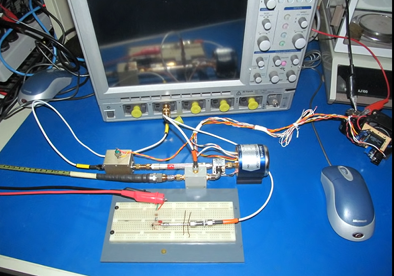
It is common wisdom that solderless breadboards are only good for low frequencies. But how fast can they really go? There’s been a contest going on to see who can make the fastest breadboard-mounted oscillator and [Joe Smith] has been trying to keep his leading position. He’s already managed 6 GHz and now he’s shooting for 20 GHz, as you can see in the video below.
One of the biggest challenges at these frequencies is just measuring your output. You may have a scope, but how does it do at 20 GHz? So half of the story is how [Joe] managed to monitor his output.
You’ll see in the video that while the breadboard is just an ordinary-looking breadboard, it is covered with strange-looking cages, feed lines, and shields. The rules prohibit using ICs and crystals, so if you want to compete, you’ll need to brush up on your RF skills.
If you enjoy this sort of thing, there are several older videos on the topic from [Joe.] We aren’t sure what practical use there is to building a microwave transmitter on a breadboard, but we get the sport of it.
We see a number of contestants that try to unseat the ubiquitous solderless breadboard, but none of them seem to stick. Maybe if it isn’t broke, there’s no need to fix it.


This is a stupid challenge and I’m jealous of everyone involved. I wonder if you could model the breadboard’s internal structure in a simulator and try to turn it into a resonator?
As I read the article, I wondered if “those people” are using the characteristics of the breadboard to their advantage.
Or at least know which pitfalls to avoid.
Right, like designing 3pf less capacitance in your resonators because you get it between the rows etc etc.
TL;DW, but this scope looks nice. Don’t want to know the price however…
Joe Smith is a bit of a mystery, but if you watch his vids you will see he has a ton of expensive and fancy gear so it’s safe to assume he is some sort of retired electronics engineer. Highly recommend his channel, the man is a casual genius.
Maybe doesn’t want a ton of people asking him about the classified anti-radar tech he was developing at Lockheed or something.
Yeah, a place I worked at 20 years ago had BERT (Bit Error Rate Test) that cost a quarter million.
They even let me touch it a couple of times!
Ok, so to check the waveform he is mixing the 15.34 GHz signal with 12 GHz, passes it through a 6 GHz lowpass and an amplifier rated for up to 8 GHz, and then displays it on an oscilloscope with 5 GHz bandwidth.
What did he expect to see if the signal was not a sine wave? If the original signal had a second or higher harmonic, it would be way beyond the bandwidth of the components even after downmixing.
Well, you might calculate your RMS signal power indicated on the scope, and it might be less than the measured output into a dummy load and a thermometer.
A more useful challenge would be for “fastest 2-sided FR4-mounted oscillator.”
I’d suggest “cleanest and most stable” MW amplifier There is a lot more to it than speed. Or cleanest 100 ps pulse if you want fast.
In my book you simply can’t beat Manhattan construction using sub-boards as shown here:
https://www.youtube.com/watch?v=vq968AFgPhg
It’s simple and quick with well controlled impedances where needed.
This started on EEVblog:
https://www.eevblog.com/forum/projects/challenge-thread-the-fastest-breadboard-oscillator-on-the-mudball/